A Calibration Method for Joint Coordinate Measuring Machine Combined with CNC Machine Tool

A technology of coordinate measuring machines and numerical control machine tools, which is applied to measuring devices and instruments, can solve the problems of complex implementation process, lack of consideration of single-point repeatability accuracy index, and difficult calibration, so as to achieve simple manufacturing, reduce calibration costs, and reduce The effect of calibration difficulty

Active Publication Date: 2019-12-17
HANGZHOU DIANZI UNIV
View PDF8 Cites 0 Cited by
  • Summary
  • Abstract
  • Description
  • Claims
  • Application Information

AI Technical Summary

Problems solved by technology

"An Optimal Sampling Strategy for Structural Parameter Calibration of a Portable Articulated Coordinate Measuring Machine" (Tool Technology, 2012) uses a quartz rod with cone dimples at both ends for calibration, and places the quartz rod at six circumferential positions where the measuring machine is the center of the circle At each position, 500 sets of data were measured by rotating the quartz rod in different planes with a certain division, a total of 3,000 sets of data; although such a sampling strategy can satisfy the entire measurement space, the implementation process is complicated, and at the same time, it does not consider Single-point repeatability is the precision indicator
[0005] The above methods still have deficiencies in calibration. During the calibration process, high-precision measuring instruments or high-precision auxiliary calibration tools are required, and it is difficult to calibrate in the field.

Method used


Image

  • A Calibration Method for Joint Coordinate Measuring Machine Combined with CNC Machine Tool
  • A Calibration Method for Joint Coordinate Measuring Machine Combined with CNC Machine Tool
  • A Calibration Method for Joint Coordinate Measuring Machine Combined with CNC Machine Tool

Examples


Embodiment Construction

[0035] The present invention will be described in detail below in conjunction with the accompanying drawings and embodiments.

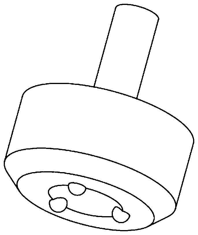
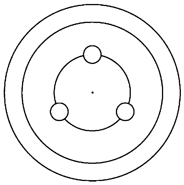
[0036] Such as figure 1 and2 As shown in Fig. 1, a method for calibrating an articulated coordinate measuring machine combined with a CNC machine tool, the three-ball and cone-socket calibration tool used is a special shaft part, including an integrally formed small shaft section and a large shaft section; the small shaft section is clamped on the CNC On the main shaft 1 of the machine tool; the end face of the large shaft section is provided with a tapered hole, and the tapered hole is located on the circumference of the end face of the large shaft section, and three spheres uniformly distributed along the circumferential direction are fixed on the tapered hole. The three-ball cone-socket calibration tool uses magnetic materials.

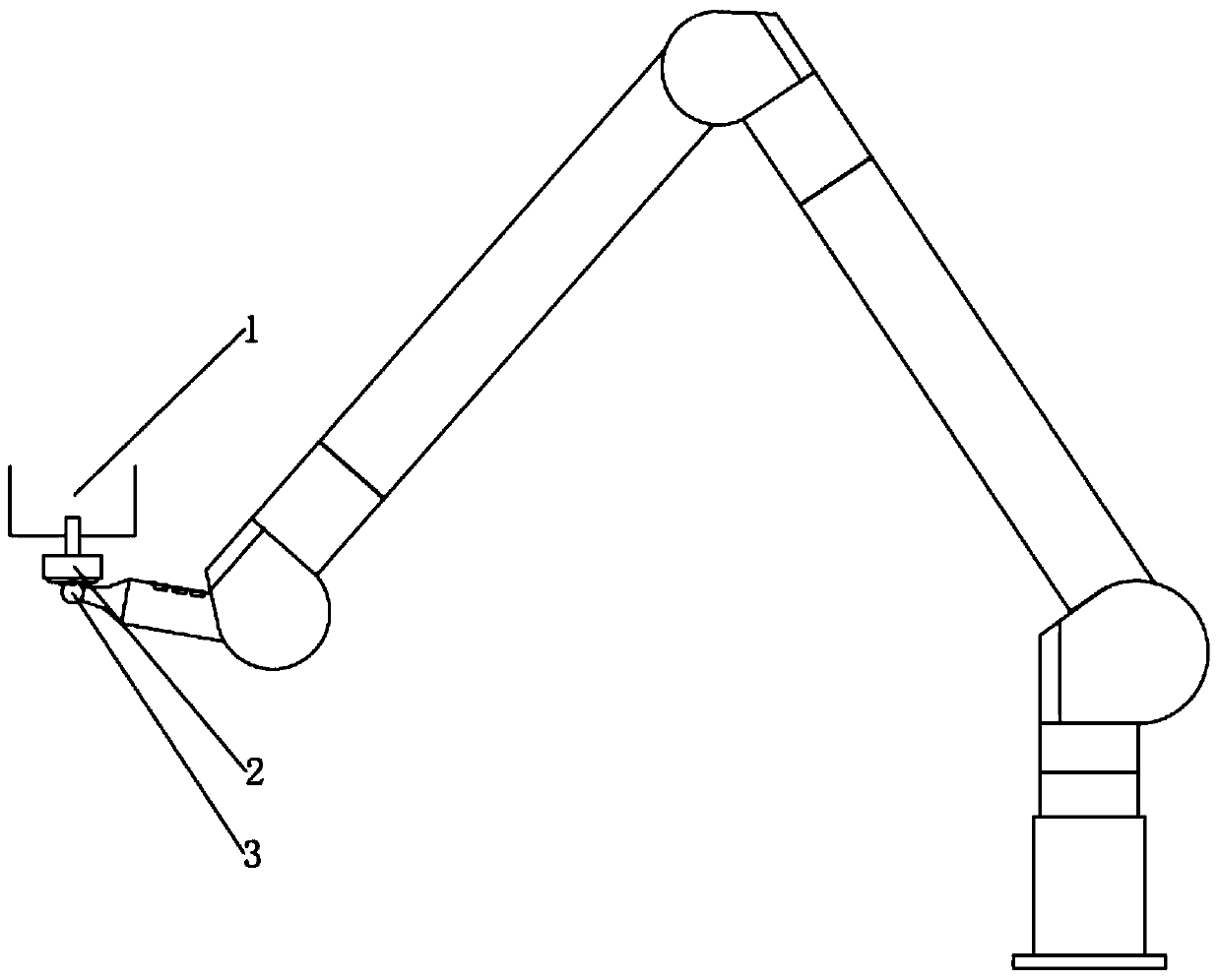
[0037] Such as image 3 As shown, during the data acquisition process, when the spherical probe 3 of the measuring mac...


PUM


Abstract

The invention discloses a calibration method for an articulated coordinate measuring machine combined with a numerical control machine tool. The existing measuring machine calibration method requires the use of high-precision measuring instruments or auxiliary calibration tools, and on-site calibration is difficult. In the present invention, a three-ball and cone-socket calibration tool is clamped on the spindle of a numerically controlled machine tool, and a virtual calibration rod is set in a defined measurement area; the virtual calibration rod is a sequence of t measuring points arranged equidistantly; the cone of the three-ball and cone-socket calibration tool The center of the hole is positioned to each measuring point in turn; after positioning to a certain measuring point, the spherical probe of the calibration machine is embedded in the taper hole of the three-ball cone-socket calibration tool for data sampling; Measure the cone hole center of the three-ball cone-socket calibration tool n times at different attitudes; process the probe coordinates obtained after data sampling to obtain the optimal solution for the structural parameter vector A of the calibration machine. The invention adopts the numerical control machine tool as the calibration instrument, which improves the site environment adaptability of the calibration method and reduces the cost.

Description

technical field [0001] The invention belongs to the technical field of coordinate measurement, and in particular relates to a calibration method for an articulated coordinate measuring machine combined with a numerical control machine tool. Background technique [0002] The articulated coordinate measuring machine is a multi-degree-of-freedom coordinate measuring machine, which consists of a measuring arm and a rotating joint connected in series to form an open chain structure. Compared with the traditional three-coordinate measuring machine with orthogonal coordinate system, it has the advantages of small size, large measurement range, convenience and flexibility, and good environmental adaptability. However, due to the shortcomings of accumulative error amplification in this series structure, the structural parameter errors of joints at all levels will be amplified step by step, resulting in a decrease in its accuracy. In order to improve the measurement accuracy of the m...

Claims


Application Information

Patent Timeline
Patent Type & Authority Patents(China)
IPC IPC(8): G01B21/04
CPCG01B21/042
Inventor 王文翁一新高贯斌时光杨贺卢科青
Owner HANGZHOU DIANZI UNIV
Why Eureka
Try Eureka