Omnidirectional slip sensor

A sensor and omni-directional technology, applied in the field of slip sensor, can solve the problem of not being able to measure the direction and speed of sliding, and achieve the effect of convenient production and high sensitivity

Pending Publication Date: 2018-11-16
SHENZHEN GRADUATE SCHOOL TSINGHUA UNIV
View PDF0 Cites 4 Cited by
  • Summary
  • Abstract
  • Description
  • Claims
  • Application Information

AI Technical Summary

Problems solved by technology

Although some slip sensors can identify whether sliding occurs, they cannot measure the direction

Method used


Image

  • Omnidirectional slip sensor
  • Omnidirectional slip sensor
  • Omnidirectional slip sensor

Examples


preparation example 1

[0039] In this preparation example, a slip sensor based on a single-electrode nanogenerator is fabricated through some devices, which specifically includes the following steps:

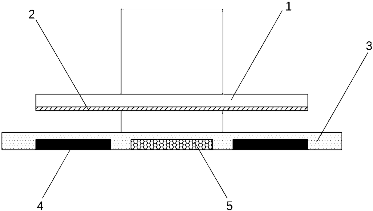
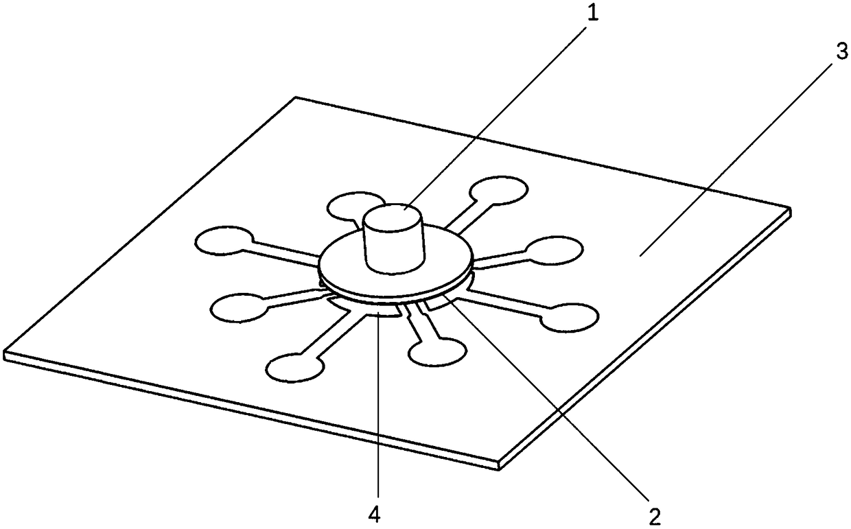
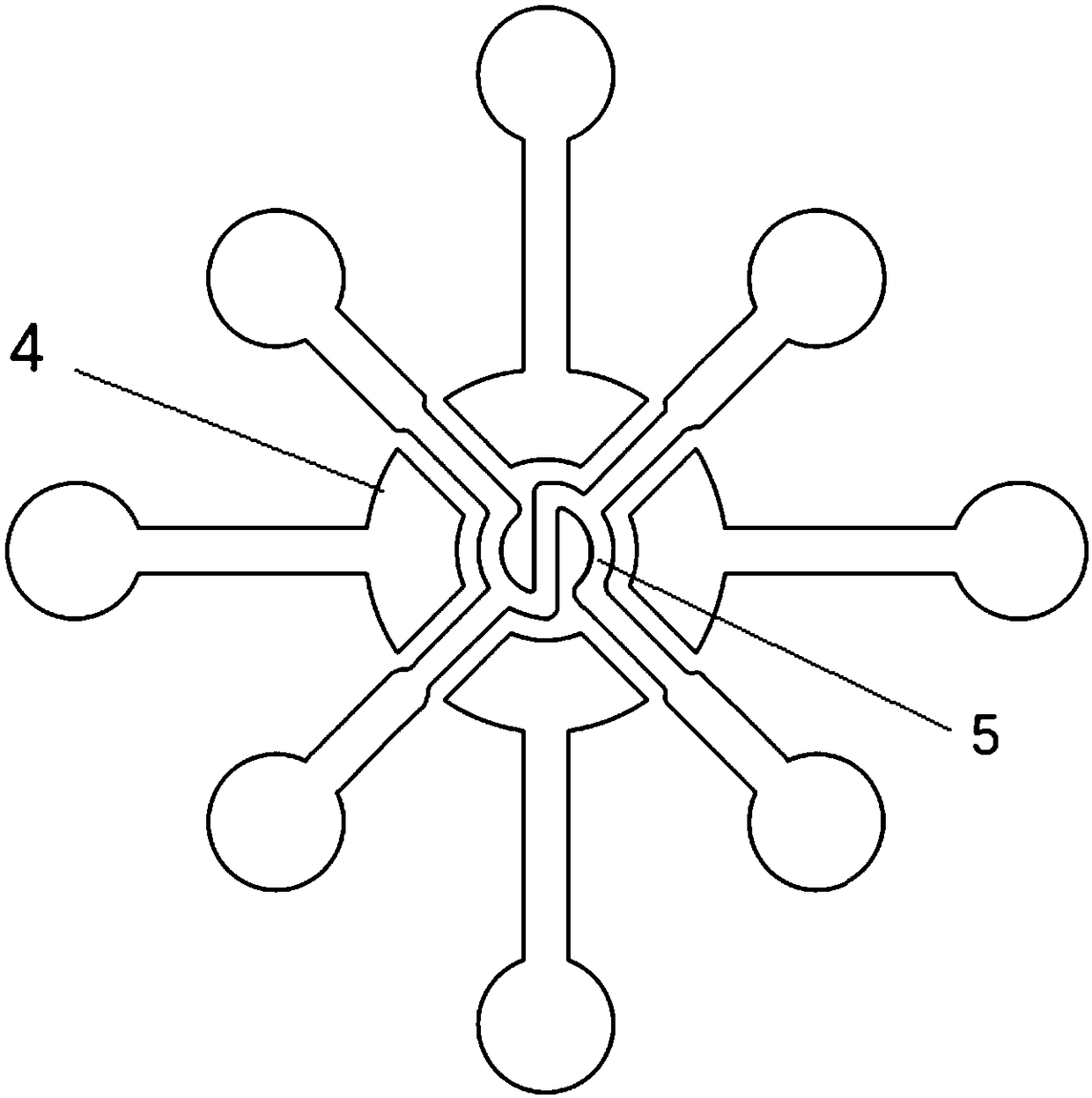
[0040] 1) First, print two tough resin molds by a laser 3D printer, one of which is a model array with a large circular groove in the middle containing a small circular groove, wherein the large circular groove is 7 mm in diameter and 380 microns in depth; the diameter of the small circular groove 3 mm deep and 750 microns; the other mold is an array of circular grooves, 3 mm in diameter and 2.5 mm deep. Wash the two molds with deionized water, then blow dry with nitrogen;

[0041] 2) Mix the PDMS prepolymer and the curing agent in the ratio of 10:1 on the electronic scale, and pour the mixed PDMS into the mold after fully stirring, and use a vacuum pump to perform three vacuum treatments to remove the excess air in the PDMS, Put the mold in an oven at 50°C for 3 hours;

[0042] 3) Peel off the PDMS...

preparation example 2

[0046] Preparation example 2: The difference between this preparation example and preparation example 1 is that the parameters such as the sensor structure size and the materials used for the electrodes are different.

[0047] In this embodiment, a slip sensor based on a single-electrode nanogenerator is fabricated through some devices, which specifically includes the following steps:

[0048] 1) First, print a PLA mold by a thermosetting 3D printer. One of the molds is a model array with a large circular groove in the middle containing a small circular groove. The large circular groove has a diameter of 8 mm and a depth of 600 microns; the diameter of the small circular groove is 3 mm deep 2 mm; the other mold is an array of circular grooves, circular grooves 3 mm in diameter and 5 mm deep. Wash the mold with deionized water, then blow dry with nitrogen;

[0049] 2) Mix the PDMS prepolymer and the curing agent in the ratio of 10:1 on the electronic scale, and pour the mixed ...


PUM

PropertyMeasurementUnit
Diameteraaaaaaaaaa
Heightaaaaaaaaaa
Diameteraaaaaaaaaa

Abstract

Provided is an omnidirectional slip sensor. The omnidirectional slip sensor comprises an upper structure and a lower structure, the upper structure is a cylindrical structure with a circular skirt edge, the material of the upper structure is a flexible material, the lower surface of the skirt edge is provided with an upper electrode, the lower structure comprises a piezoresistive film, a pluralityof lower electrodes, and an insulation film covering the piezoresistive film and the plurality of lower electrodes, the plurality of lower electrodes are distributed at intervals around the outside of the piezoresistive film, the piezoresistive film is located at the center surrounded by the plurality of lower electrodes, the lower surface of the cylindrical structure is aligned with the piezoresistive film, when a shearing force is applied to the sensor, the upper structure inclines towards the direction of the force to enable the upper electrode to make contact with the insulation film below, electric signals are inducted between the upper electrode and the lower electrodes under the insulation film, and when a normal pressure is applied to the sensor, the piezoresistive film is normally deformed, and a resistance thereof is changed. According to the omnidirectional slip sensor, sliding in any direction can be identified, and the sliding speed and the shearing force can also be measured.

Description

technical field [0001] The present invention relates to a sliding sensor, in particular to an omnidirectional sliding sensor. Background technique [0002] When the manipulator grasps the object, it is necessary to monitor the relative movement between the manipulator and the contact surface of the held object in real time, so as to determine the appropriate grip force value and grasp the object without damaging the object. The sliding sensor is a device mainly used to detect the sliding or pre-sliding between the manipulator and the held object, and its performance directly determines whether the robot can successfully complete the flexible grasping task. [0003] The developed slip sensors are mainly based on piezoelectric, piezoresistive, capacitive and other principles. Although some sliding sensors can identify whether sliding occurs, they cannot measure the direction and speed of sliding or can only measure the direction and speed of sliding in a single direction. S...

Claims


Application Information

Patent Timeline
IPC IPC(8): G01D5/16
CPCG01D5/16
Inventor 张旻肖聿翔梁家铭钱翔董瑛王晓浩
Owner SHENZHEN GRADUATE SCHOOL TSINGHUA UNIV
Why Eureka
Try Eureka