
MIMO radar target direction rapid estimation method based on partial correlation waveform

A technology of partial correlation and target direction, which is applied in the field of MIMO radar target angle estimation, which can solve the problems of unsuitable engineering application, large amount of calculation, and unsuitable related waveforms.

Active Publication Date: 2018-11-16
XIDIAN UNIV
View PDF7 Cites 2 Cited by
  • Summary
  • Abstract
  • Description
  • Claims
  • Application Information

AI Technical Summary

Problems solved by technology

[0003] The maximum likelihood algorithm is a super-resolution parameter estimation method, which can directly process coherent sources, and even correctly estimate the parameters of the source under a single snapshot, so it is widely used in practical engineering; MIMO radar is The existing method of target direction estimation is extended from the target direction estimation method of traditional phased array radar, such as the MIMO radar target estimation algorithm based on maximum likelihood, I.Bekkerman, J.Tabrikian, Target detection and localization using MIMO radars and sonars, IEEE Transactions on Signal Processing 54(10)(2006) 3873-3883; although the maximum likelihood-based MIMO radar target estimation algorithm can effectively estimate the target direction, but there is a problem of large amount of calculation, it is not suitable for engineering Application; Literature: Zhao Yongbo, Zhu Yutang, Liu Hongwei, etc. A fast method for estimating targets for MIMO radars China, 201410727711.9 [P] 2014.12.03 A fast method for estimating targets based on orthogonal waveforms is proposed, but it is not suitable for partially correlated waveforms

Method used


Image

  • MIMO radar target direction rapid estimation method based on partial correlation waveform
  • MIMO radar target direction rapid estimation method based on partial correlation waveform
  • MIMO radar target direction rapid estimation method based on partial correlation waveform

Examples


Embodiment Construction

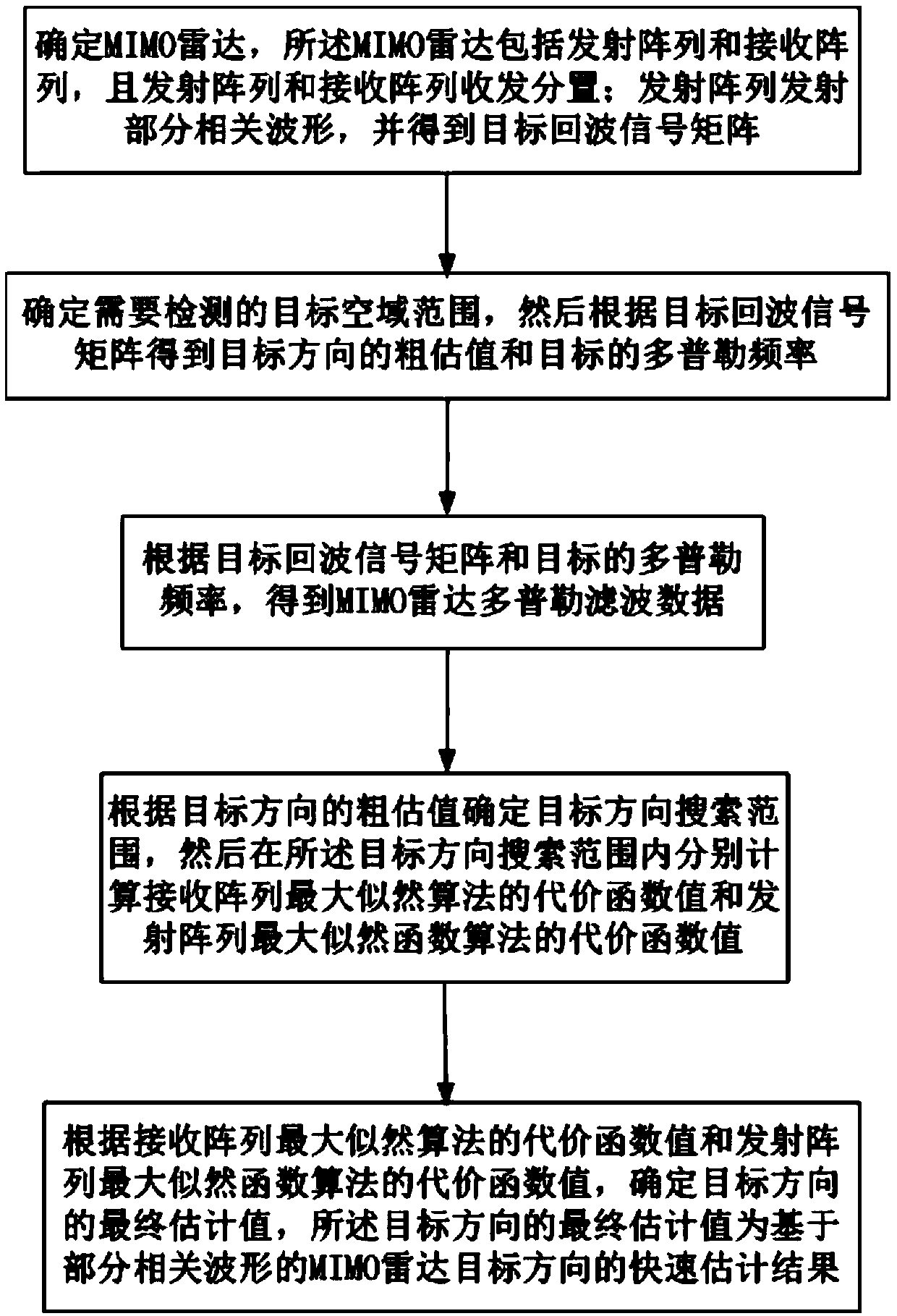
[0019] refer to figure 1 , is a flow chart of a method for rapidly estimating the direction of a MIMO radar target based on partially correlated waveforms of the present invention; wherein the method for rapidly estimating the direction of a MIMO radar target based on partially correlated waveforms comprises the following steps:

[0020] Step 1, refer to figure 2 , is the antenna array model diagram used in the present invention; as figure 1 As shown, the MIMO radar used in the present invention is an array antenna of a waveform diversity MIMO radar, including a transmitting array and a receiving array, and the transmitting array and the receiving array are separated for sending and receiving; the transmitting array includes Mt transmitting antennas, and the receiving array includes Mr receiving antennas , Mt and Mr can be the same or different, the transmitting array and the receiving array are respectively uniform and equidistant linear arrays, the interval between the Mt ...


PUM


Abstract

The present invention discloses an MIMO radar target direction rapid estimation method based on a partial correlation waveform, belongings to the technical field of radar. The method comprises the steps: determining an MIMO radar, wherein the MIMO radar comprises an emission array and a receiving array which are arranged in a transmit-receive mode; emitting the partial correlation waveform by theemission array to obtain a target echo signal matrix; determining a target airspace range requiring detection to obtain a rough assessment value of the target direction and a Doppler frequency of thetarget so as to obtain MIMO radar Doppler filtering data; determining a target direction search range, and calculating a cost function value of the maximum likelihood algorithm of the receiving arrayand a cost function value of the maximum likelihood function algorithm of the emission array in the target direction search range; and determining a final estimation value in the target direction, wherein the final estimation value in the target direction is a rapid estimation result of the MIMO radar target direction based on the partial correlation waveform.

Description

technical field [0001] The invention belongs to the field of radar technology, in particular to a method for quickly estimating the direction of a MIMO radar target based on a partially correlated waveform, which is suitable for estimating the angle of the MIMO radar target. Background technique [0002] MIMO radar is a new concept radar system based on the combination of MIMO technology in wireless communication and the basic principles of integrated pulse and aperture radar. The types of MIMO radar can be divided according to the difference in the distance between array elements. One of It is a MIMO radar with space diversity gain, and the other is a MIMO radar with waveform diversity gain; the distance between the receiving antenna elements of the MIMO radar with space diversity gain is relatively large, so the echoes received by the two receiving antenna elements The signals are independent of each other, so the MIMO radar with space diversity gain is also called distrib...

Claims


Application Information

Patent Timeline
IPC IPC(8): G01S3/14G01S3/72G01S13/02
CPCG01S3/14G01S3/72G01S13/02
Inventor 赵永波董奥覃刘宏伟何学辉苏洪涛冯大政
Owner XIDIAN UNIV
Learn More