
No-servo tracking angle measurement method for space platform object

A target angle and platform technology, applied in the field of space platform target servo-free tracking angle measurement, can solve the problems of increased volume, weight and power consumption of the angle measurement system, high requirements for the threshold value of the signal-to-noise ratio of the received signal, and limited application range, etc., to achieve Good adaptability to near and far targets, reduced volume, and the effect of avoiding disturbance

Active Publication Date: 2018-11-16
BEIJING INSTITUTE OF TECHNOLOGYGY
View PDF4 Cites 2 Cited by
  • Summary
  • Abstract
  • Description
  • Claims
  • Application Information

AI Technical Summary

Problems solved by technology

However, on the one hand, this method needs to add an additional sum-difference unit to form a sum-difference beam, and the multi-channel phased array antenna increases the volume, weight and power consumption of the angle measurement system, which is not suitable for space platform applications with demanding resources; On the other hand, this method has high requirements on the signal-to-noise ratio threshold of the received signal, which limits its application range

Method used


Image

  • No-servo tracking angle measurement method for space platform object
  • No-servo tracking angle measurement method for space platform object
  • No-servo tracking angle measurement method for space platform object

Examples


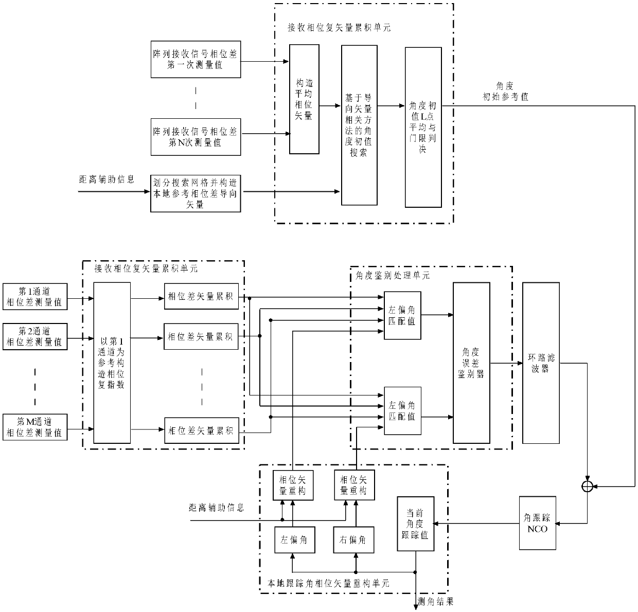
Embodiment Construction

[0027] The present invention will be described in detail below with reference to the accompanying drawings and examples.

[0028] The present invention provides a method for measuring the angle of a space platform target without servo tracking. The method first uses an angle search algorithm to estimate the initial value of the angle of a large field of view, and then uses an angle tracking ring to track the angle of the target. Referring to the drawings and embodiments below, The present invention is described in further detail:

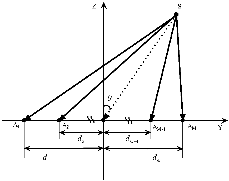
[0029] Before the method of the present invention is implemented, according to the range of angles that the target may appear, design and select a wide-angle (large field of view) antenna unit, and complete the configuration design of the antenna array. The configuration of the antenna array has no specific requirements, and the antenna array can be directly fixed. Installed on the space platform, it is used to receive the echo or radiation wireless...


PUM


Abstract

The invention discloses a no-servo tracking angle measurement method for a space platform object, and the method comprises the steps: completing the estimation of an initial value of a big view anglethrough an angle search algorithm; carrying out the target angle tracking through an angular tracking ring. The method can reduce the calculation burden of the tracking and calculation of a target angle, and improves the precision.

Description

technical field [0001] The invention belongs to the technical field of microwave radar measurement, and in particular relates to a non-servo tracking angle measurement method for a space platform target. Background technique [0002] Angle measurement of space targets is the key to space-based space target detection and positioning. For general radars, narrow beams are usually used to transmit and receive signals, and the coverage of the detection airspace is achieved through mechanical scanning or electronic scanning of the beams. Therefore, the rate of time-sharing detection of targets at different positions in a large field of view is low. Under spaceborne conditions, the mechanical scanning of the radar antenna is not only a weak link in reliability, but also brings certain disturbances to the attitude stability of the satellite. The electronically scanned phased array antenna is complex to implement, and the high-frequency T / R components have low efficiency, large volu...

Claims


Application Information

Patent Timeline
Patent Type & Authority Applications(China)
IPC IPC(8): G01S13/68
CPCG01S13/68
Inventor 崔嵬姚杰韩月涛吴嗣亮梁艺宝沈清
Owner BEIJING INSTITUTE OF TECHNOLOGYGY
Learn More