
An ultra-high resolution imaging optical system and imaging method for submicron pixels

An ultra-high-resolution, sub-micron-level technology, applied in the field of optical design, can solve problems such as difficult to meet, large focal length aperture, etc., to achieve the effect of improving manufacturability, reducing difficulty of focusing, and ensuring integration performance

Active Publication Date: 2021-02-05
BEIJING RES INST OF SPATIAL MECHANICAL & ELECTRICAL TECH
View PDF1 Cites 0 Cited by
  • Summary
  • Abstract
  • Description
  • Claims
  • Application Information

AI Technical Summary

Problems solved by technology

[0006] The technical problem solved by the present invention is: in view of the relatively large focal length and aperture of the traditional optical system in the current prior art, it is difficult to meet the requirement of a relatively small focal length and aperture ratio matched by the ultra-high sampling frequency, and a submicron-level pixel is proposed. Ultra-high resolution imaging optical system and imaging method

Method used


Image

  • An ultra-high resolution imaging optical system and imaging method for submicron pixels
  • An ultra-high resolution imaging optical system and imaging method for submicron pixels
  • An ultra-high resolution imaging optical system and imaging method for submicron pixels

Examples


Embodiment Construction

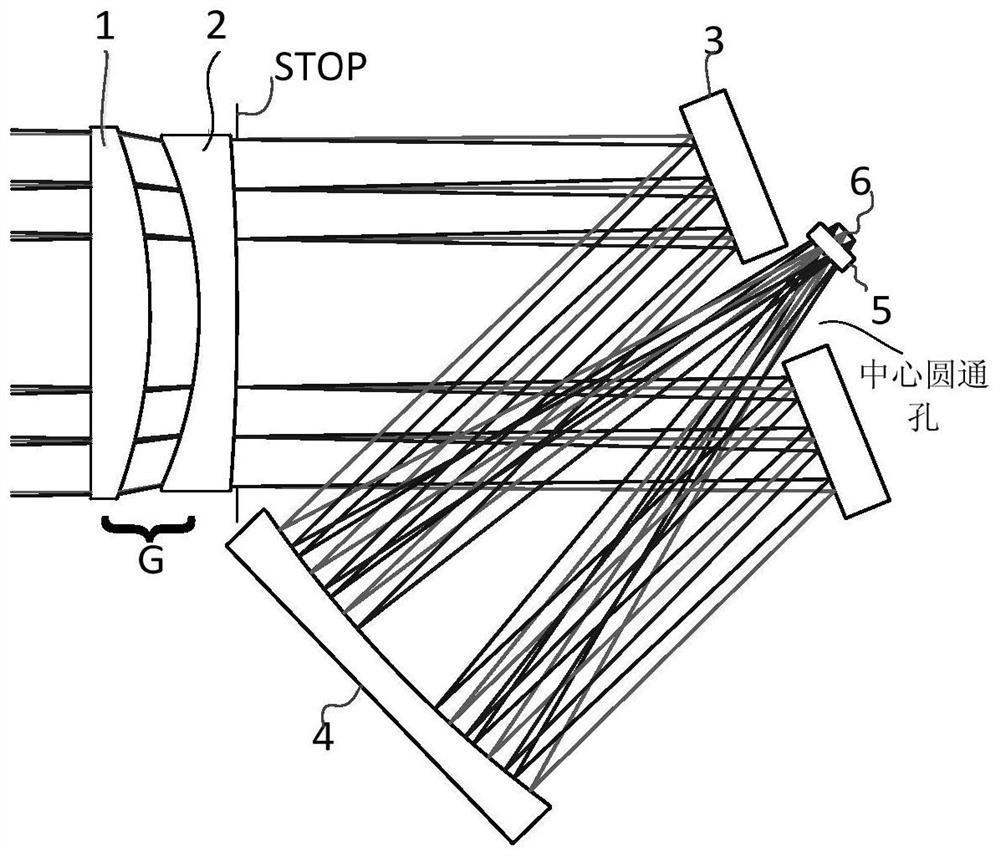
[0033] An ultra-high resolution imaging optical system with submicron pixels, such as figure 1 As shown, it includes a first aspheric correction mirror 1, a second aspheric correction mirror 2, a folding mirror 3, a main reflector 4, a field lens 5, and an imaging image surface 6. The first aspheric correction mirror 1, the second aspheric correction mirror Two aspheric correction mirrors 2 are arranged side by side on the incident light path to form a correction mirror group, and the folding mirror 3 is arranged on the rear side of the correction mirror group and is inclined at a certain angle to the vertical direction of the incident light path. The field mirror 5 is installed on the rear side of the through hole position, and the installation position of the main reflector 4 is adjusted according to the turning angle of the turning mirror 3 and the distance between the center of curvature of the main reflecting mirror 4 and the center position of the turning mirror 3 to ensu...


PUM

PropertyMeasurementUnit
radiusaaaaaaaaaa

Abstract

An ultra-high-resolution imaging optical system and imaging method for submicron-scale pixels, comprising a first aspherical correction mirror (1), a second aspherical correction mirror (2), a folding mirror (3), and a main reflection mirror (4), the field lens (5), and the imaging image plane (6), through the reflection of the correcting mirror group and the refracting mirror (3), and then the main reflecting mirror (4) converges to the imaging image in the field lens (5) It overcomes the problem that the existing optical system cannot cope with the large-diameter high-precision optical detector of the correction mirror, and is suitable for the existing optical detection device.

Description

technical field [0001] The invention relates to an ultra-high resolution imaging optical system and an imaging method of a submicron-level pixel, belonging to the technical field of optical design. Background technique [0002] The imaging detector is the key core device of the space optical remote sensing camera, and the pixel size and pixel density of the detector are key indicators that affect the camera's capabilities. Traditional spaceborne high-resolution imaging remote sensors generally use detectors with pixel sizes above 7 μm. With the development of commercial remote sensing technology, more and more micro-nano satellite payloads use detectors with small pixel sizes to reduce the cost of system implementation. Imaging devices with small pixel size are one of the ways to realize the payload of tiny satellites. [0003] In recent years, with the development of semiconductor technology and imaging detector technology, the pixel size has exceeded 1um. Internationall...

Claims


Application Information

Patent Timeline
Patent Type & Authority Patents(China)
IPC IPC(8): G02B17/08
CPCG02B17/0808G02B17/0852
Inventor 刘晓林阮宁娟庄绪霞胡嘉宁李妥妥王保华张庭成穆生博梅强魏久哲
Owner BEIJING RES INST OF SPATIAL MECHANICAL & ELECTRICAL TECH
Learn More