A combined converter and its control method

A control method and converter technology, which are applied in AC network circuits, wind power generation, electrical components, etc., can solve the problems of limited mechanical life and electrical life of frame circuit breakers.

Active Publication Date: 2021-04-13
SUNGROW POWER SUPPLY CO LTD
View PDF3 Cites 0 Cited by
  • Summary
  • Abstract
  • Description
  • Claims
  • Application Information

AI Technical Summary

Problems solved by technology

[0005] However, the inventors found that the mechanical life and electrical life of the frame circuit breaker are limited. In the actual grid-connected operation, it is necessary to reduce the number of disconnection of the converter, that is, reduce the number of times the frame circuit breaker operates

Method used


Image

  • A combined converter and its control method
  • A combined converter and its control method
  • A combined converter and its control method

Examples


Embodiment Construction

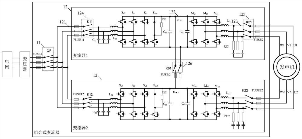
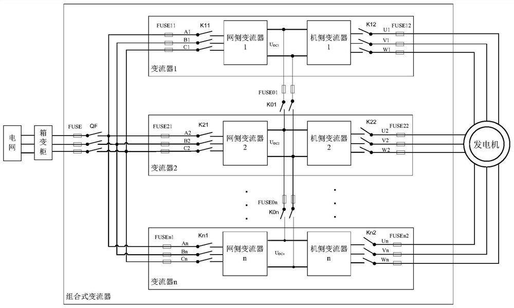
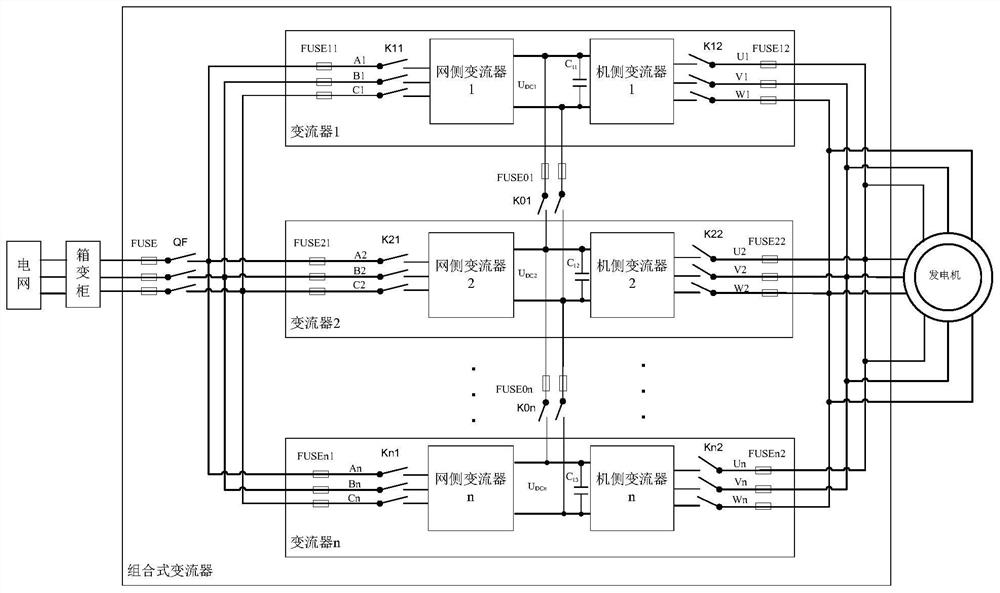
[0055] see figure 1 , figure 1 A schematic structural diagram of a combined converter provided by an embodiment of the present invention, the combined converter includes a frame circuit breaker 11 and at least two converters 12 . Wherein, each converter 12 includes an AC grid side 121 , a DC side 122 , an AC motor side 123 , a first contactor 124 and a second contactor 125 .

[0056] Specifically, the connection relationship of each device in the combined converter is:

[0057] The grid-side AC output terminal 121 of each converter 12 is connected to one end of the frame circuit breaker 11 through the first contactor 124, and the other end of the frame circuit breaker 11 is connected to the grid;

[0058]The AC motor side 123 of each converter 12 is electrically connected to the generator 13 through the second contactor 125;

[0059] The DC sides 122 of the plurality of converters 12 are all connected in parallel through the third contactor 126 .

[0060] It can be seen fr...


PUM


Abstract

Embodiments of the present invention provide a combined converter and a control method. The combined converter includes a frame circuit breaker and at least two converters, wherein each converter includes an AC grid side, a DC side, AC motor side, first contactor, and second contactor. The combined converter provided in this solution, by controlling the switching status of the first contactor, the second contactor and the third contactor, independently controls the connection status of each converter, which improves the redundancy of the system . At the same time, the frame circuit breaker can always be in the closed state, that is, the number of breaking times of the frame circuit breaker is reduced, thereby prolonging the service life of the frame circuit breaker. In addition, since multiple converters connected to the system are connected in parallel through the third contactor, the circulating current between the converters is reduced.

Description

technical field [0001] The invention relates to the technical field of new energy motor control, in particular to a combined converter and a control method. Background technique [0002] The converter is a device commonly used in the power generation system to convert the AC power on the grid side into DC power, and then convert the DC power into AC power on the motor side. It includes a plurality of parallel semiconductor switches. - Conversion of direct current. Specifically, the semiconductor switch may be a device having a switching function such as an IGBT, an IGCT, and an IEGT. [0003] As the power requirements of the power generation system become higher and higher, usually the AC sides of multiple converters are connected in parallel to meet the larger power requirements. However, the AC side of multiple converters is directly connected in parallel, and the DC side is not paralleled. In order to make the system redundant, a frame circuit breaker is installed on th...

Claims


Application Information

Patent Timeline
Patent Type & Authority Patents(China)
IPC IPC(8): H02J3/38
CPCH02J3/386H02J3/38Y02E10/76
Inventor 汪令祥周俭节
Owner SUNGROW POWER SUPPLY CO LTD
Why Eureka
Try Eureka