Full-automatic punching riveting system and working process thereof

A stamping riveting, fully automatic technology, applied in the direction of forming tools, manufacturing tools, metal processing equipment, etc., can solve the problems of affecting efficiency, low production efficiency, high cost, etc.

Pending Publication Date: 2018-11-20
SUZHOU KEYTEC PRECISION COMPONENTS
View PDF0 Cites 11 Cited by
  • Summary
  • Abstract
  • Description
  • Claims
  • Application Information

AI Technical Summary

Problems solved by technology

[0002] In the field of stamping, it is often necessary to rivet the stamped product and the rivet. The traditional production process is to stamp out the semi-finished product first, and then complete the riveting of the stamped semi-finished product and the rivet through secondary processing, and then continue the subsequent processing procedures, such as cutting and bending. etc. Due to the need for multiple production processes, the production efficiency is low, the producti

Method used


Image

  • Full-automatic punching riveting system and working process thereof
  • Full-automatic punching riveting system and working process thereof
  • Full-automatic punching riveting system and working process thereof

Examples


Embodiment 1

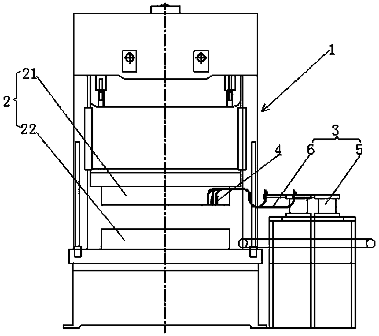
[0056] as attached figure 1 , 2 As shown, a kind of full-automatic stamping riveting system of the present invention comprises punching machine 1, mold 2, feeder and finished product discharge conveyor belt, also includes rivet conveying device 3, positioning ejection device 4 and control center; The feeder is used for Stamping continuous die provides flat material, and according to stroke accuracy requirements, completes feeding smoothly at an appropriate speed, and cooperates with the action of punch press and mold; the control center is used to control the movement of punch press, mold, rivet conveying positioning detection device and feeder Coordination Consistent, so that the entire automatic stamping die riveting system can run safely and efficiently; the punch press 1 is an automatic punch press, and is equipped with an electronic cam; figure 2Among them, the leftmost part of the mold 2 is the stamping module, which completes the punching of the gap part of the materi...

Embodiment 2

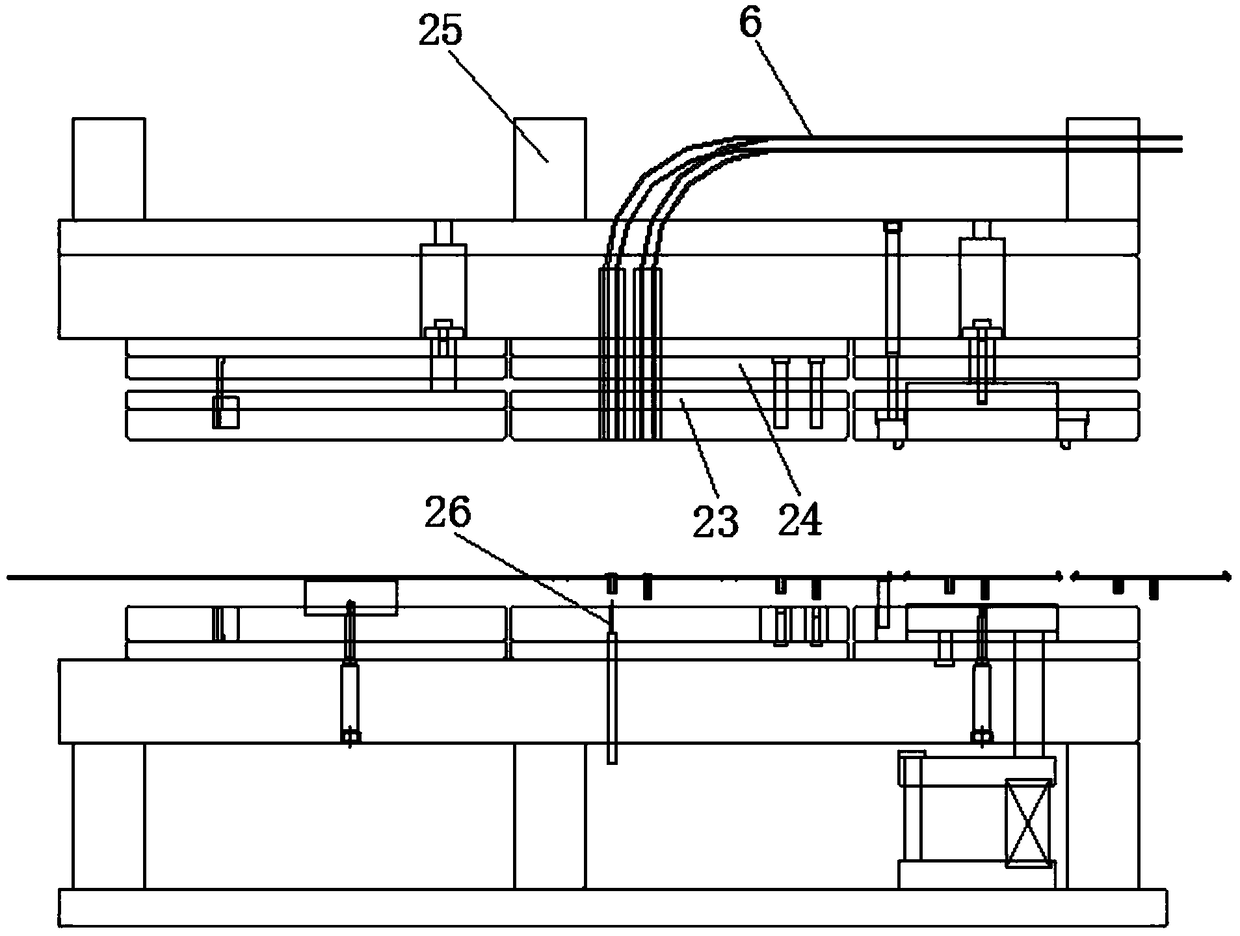
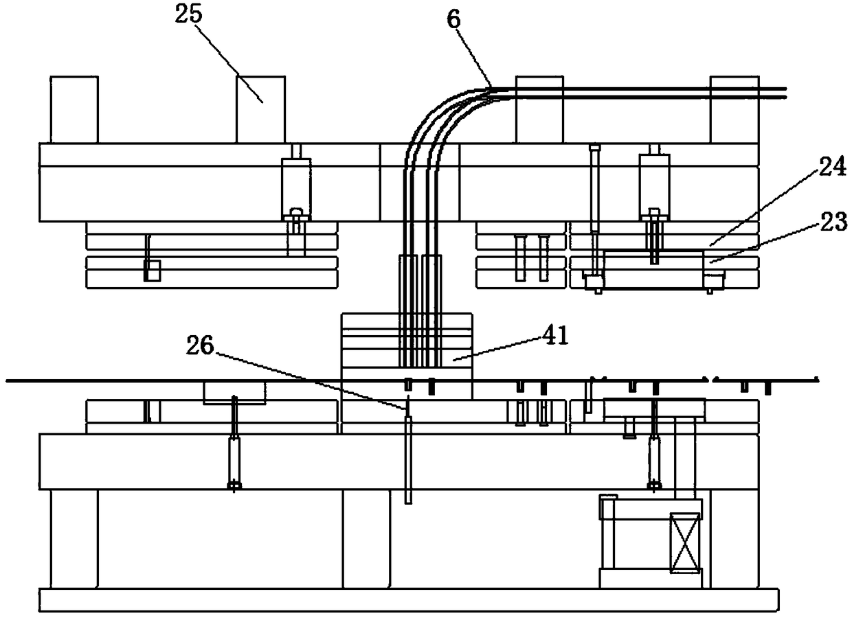
[0063] as attached figure 1 , 3 As shown, the positioning ejection device 4 is fixedly connected to the lower mold 22 through the ejection gun installation mechanism 41; the height dimension of each layer of the ejection gun installation mechanism 41 is the same as that of the upper mold. The downward movement of the stopper plate 23 and the downward movement of the laminate corresponding to the splint 24 in the ejection gun installation mechanism 41 also trigger the clamping mechanism to loosen the rivet. All the other structures are the same as in Embodiment 1.

[0064] In this embodiment, the positioning and ejecting device 4 is arranged in the overhead layer above the lower die, and an observation hole can be opened on the ejection gun installation mechanism to facilitate observation of the movement of the rivet. When a fault occurs, the operator can directly observe the positioning and ejecting device 4, It is easy to check and maintain, but in the position where the po...


PUM


Abstract

The invention discloses a full-automatic punching riveting system and a working process thereof. The system comprises a punching machine, a mold, a feeding machine, a finished product discharging conveying belt, a rivet conveying device, a positioning ejection device and a control center; the punching machine is an automatic punching machine, an electronic cam is arranged, the mold is a punching continuous mold, and the mold comprises an upper mold and a lower mold; and rivets are conveyed to the corresponding pneumatic ejection gun through the rivet conveying device. When the full-automatic punching riveting system works, the feeding machine conveys a to-be-matched material belt into the mold on the punching machine, riveting holes and other holes are punched in the punching continuous mold, the plurality of rivets are sent into the corresponding riveting holes through the pneumatic ejection guns, riveting is completed by using the punching pressing force of the punching machine, after punching, riveting and bending processes are completed on the material belt, a product is cut off and slides to the finished product discharging conveying belt, and the product is sent out of the punching machine. According to the full-automatic punching riveting system, the machining efficiency is high, and the finished product yield is high.

Description

technical field [0001] The invention relates to an in-mold riveting device, in particular to a fully automatic punching riveting system and its working process. Background technique [0002] In the field of stamping, it is often necessary to rivet the stamped product and the rivet. The traditional production process is to stamp out the semi-finished product first, and then complete the riveting of the stamped semi-finished product and the rivet through secondary processing, and then continue the subsequent processing procedures, such as cutting and bending. etc. Due to the need for multi-channel production processes, the production efficiency is low, the production process is complicated, and multiple equipments are required, the cost is high, and the equipment occupies the workshop space. In the prior art, electric cylinders are also used to drive cantilever feeding or robot feeding, and fixtures are used to grab and place rivets. However, when the cantilever and mechanical...

Claims


Application Information

Patent Timeline
IPC IPC(8): B21J15/12B21J15/28B21J15/32B21J15/38B21D37/10B21D35/00
CPCB21D35/001B21D37/10B21J15/12B21J15/28B21J15/32B21J15/38
Inventor 卫晓能徐从青
Owner SUZHOU KEYTEC PRECISION COMPONENTS
Why Eureka
Try Eureka