Fast replacement method and device for main material of power transmission line iron tower

A technology for a transmission line tower and a replacement method, which is applied in the field of transmission line towers, can solve the problems of many construction links, transmission line accidents, and large construction area, so as to ensure normal power consumption, reduce labor costs, and reduce construction area. Effect

Pending Publication Date: 2018-11-20
JINZHOU ELECTRIC POWER SUPPLY COMPANY OF STATE GRID LIAONING ELECTRIC POWER SUPPLY +1
View PDF0 Cites 3 Cited by
  • Summary
  • Abstract
  • Description
  • Claims
  • Application Information

AI Technical Summary

Problems solved by technology

[0002] With the development and construction of transmission lines and the geological and terrain conditions of transmission lines are becoming more and more complex, it is inevitable to encounter natural disasters such as mountain collapses, earthquakes, or man-made damage to the transmission line tower, causing serious accidents to the transmission line and endangering the line. normal operation
[0003] At present, the main material replacement method of transmission line towers is to use cranes to lift and replace the towers. Since most transmission line towers are built in mountains, hills, and fields, this involves temporary land occupation. If construction is carried out in fields, land needs to be occupied. 1.5 to 2 acres, if blocked by local people, it will bring a lot of trouble to the construction work, and the required construction cost will reach 15,000 to 30,000 yuan. In addition, power outages will be required for construction, resulting in many construction links
[0004] To sum up, the existing methods for replacing the feet of transmission towers have high work intensity, large construction area, high labor costs, and temporary power outages, which affect the normal power consumption of enterprises and residents.

Method used


Image

  • Fast replacement method and device for main material of power transmission line iron tower
  • Fast replacement method and device for main material of power transmission line iron tower

Examples


Embodiment Construction

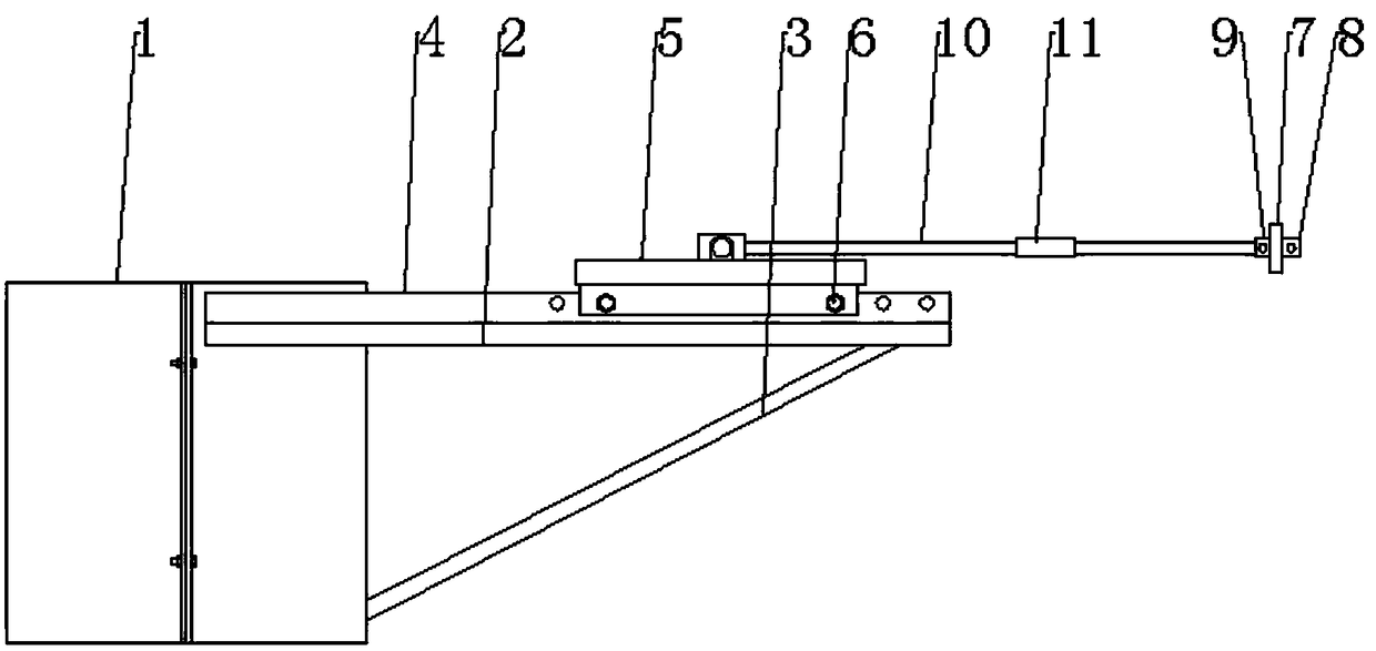
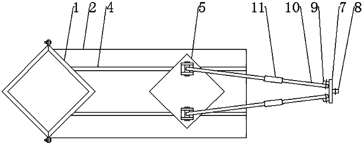
[0023] Such as figure 1 , figure 2 As shown, the quick replacement device for the main material of the transmission line iron tower includes a tower foot fixing seat, a connecting pendant, and a support rod connected between the tower foot fixing seat and the connecting pendant; The square fixed sleeve 1 composed of connected right-angle fixed sleeve splits, the horizontal support plate 2 fixed on the top of the right-angled fixed sleeve split, the bottom surface connected between the bottom surface of the horizontal support plate 2 and the right-angled fixed sleeve split bottom where it is located Oblique support 3, the guide rail 4 that is fixed on the top surface of the horizontal support plate 2, the slide plate 5 that slides with the guide rail 4, and the positioning bolt 6 that is connected between the guide rail 4 and the slide plate 5 are formed; 1. The first ear plate 8 that is located on one side of the connecting plate 7 and connected with the iron tower body of t...


PUM


Abstract

The invention relates to a fast replacement method and device for a main material of a power transmission line iron tower. The method specifically includes the following steps of connecting a cable between a tower body of the power transmission line iron tower on the side opposite to the main material to be replaced and the ground; mounting a tower foot fixing base on a tower foot foundation wherean originally damaged main material segment of the power transmission line iron tower is located; mounting a connector on the side where the originally damaged main material segment of the power transmission line iron tower is located; connecting a support rod adjustable in length between the outer side of the tower foot fixing base and the connector, and adjusting the length of the support rod so that the support rod is firmly supported between the tower foot fixing base and the connector; removing and replacing the damaged main material of the power transmission line iron tower with a new main material; removing a tower foot fixing plate, the connector and the support rod; removing the cable connected between the tower body of the power transmission line iron tower and the ground. According to the method and device, the work intensity can be reduced, the construction area is decreased, the labor cost is reduced, there is no need to cut off power, and the normal use of electricity byenterprises and residents is ensured.

Description

technical field [0001] The invention relates to an iron tower of a power transmission line, in particular to a method and a device for quickly replacing the main material of an iron tower of a power transmission line. Background technique [0002] With the development and construction of transmission lines and the geological and terrain conditions of transmission lines are becoming more and more complex, it is inevitable to encounter natural disasters such as mountain collapses, earthquakes, or man-made damage to the transmission line tower, causing serious accidents to the transmission line and endangering the line. normal operation. [0003] At present, the main material replacement method of transmission line towers is to use cranes to lift and replace the towers. Since most transmission line towers are built in mountains, hills, and fields, this involves temporary land occupation. If construction is carried out in fields, land needs to be occupied. 1.5-2 mu, if blocked ...

Claims


Application Information

Patent Timeline
IPC IPC(8): E04H12/34E04G23/02
CPCE04G23/0218E04H12/34
Inventor 李卫民吕大勇王军王恩详吴坤
Owner JINZHOU ELECTRIC POWER SUPPLY COMPANY OF STATE GRID LIAONING ELECTRIC POWER SUPPLY
Why Eureka
Try Eureka