Drainage-type furnace body structure

A furnace body structure and drainage port technology, which is applied in the field of drainage furnace body structure, can solve the problems of corrosion damage of the furnace lining metal furnace body, inability to discharge equipment with liquid water, and corrosion of the metal furnace body, so as to avoid premature failure and ensure Stable and effective work, the effect of prolonging the service life

Active Publication Date: 2018-11-20
湖南烁科热工智能装备有限公司
View PDF6 Cites 0 Cited by
  • Summary
  • Abstract
  • Description
  • Claims
  • Application Information

AI Technical Summary

Problems solved by technology

The general air roller furnace cannot meet the production process requirements, while the conventional atmosphere-protected sealed roller furnace can meet the atmosphere conditions of the material heat treatment process, but there is no drainage structure at the bottom of the furnace body, the bottom of the heating box and the bottom of the transmission box, and it is impossible to heat treat high-nickel materials. The liquid water produced in the process of ternary materials is discharged out of the equipment in time, which will lead to water accumulation in the equipment; at the same time, during the high-temperature synthesis process of high-nickel ternary lithium battery materials, there are molten alkaline oxides Li2O and strong alkalis LiOH, which dissolve Exacerbated corrosion of furnace lining refractory materials and metal furnace body after being exposed to water
In the end, the furnace lining and the metal furnace body were quickly corroded and damaged, and major repairs were required to ensure the normal operation and production of the equipment

Method used


Image

  • Drainage-type furnace body structure
  • Drainage-type furnace body structure
  • Drainage-type furnace body structure

Examples


Embodiment Construction

[0029] The present invention will be described in further detail below in conjunction with the accompanying drawings and specific embodiments.

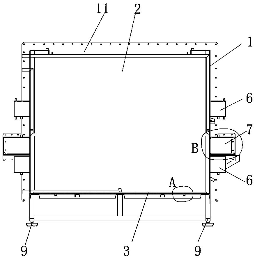
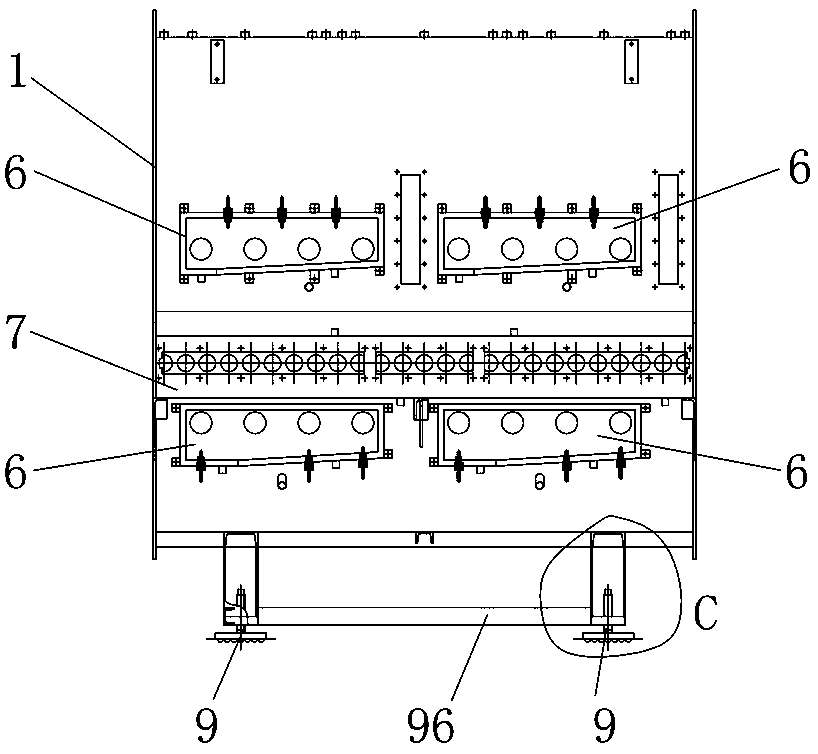
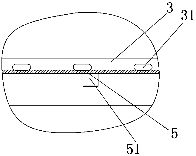
[0030] like Figure 1 to Figure 8 As shown, the drainage type furnace body structure of the present embodiment includes a shell 1 and a furnace cavity 2 surrounded by the shell 1. A plurality of U-shaped support plates 3 are arranged on the bottom wall of the furnace cavity 2, and the openings of the U-shaped support plates 3 Facing the bottom wall of the furnace cavity 2, and a plurality of U-shaped support plates 3 are arranged at intervals along the conveying direction, the side walls of the U-shaped support plates 3 are provided with a plurality of water outlets 31 arranged at intervals perpendicular to the conveying direction, and the bottom of the housing 1 is provided with There is the first drain 5 that can discharge the water of the bottom wall of the furnace cavity 2 .

[0031] In practical application, a layer of corrosion...


PUM


Abstract

The invention discloses a drainage-type furnace body structure. The drainage-type furnace body structure comprises a shell and a furnace chamber surrounded by the shell; a plurality of U-shaped supporting plates are arranged on the bottom wall of the furnace chamber, openings of the U-shaped supporting plates face the bottom wall of the furnace chamber, and the multiple U-shaped supporting platesare arranged in the conveying direction at intervals; a plurality of water passing openings formed at intervals are formed in the side walls of the U-shaped supporting plates in the direction perpendicular to the conveying direction; and the bottom of the shell is provided with a first drainage opening capable of draining water on the bottom wall of the furnace chamber. According to the drainage-type furnace body structure, a special drainage structure is arranged at the bottom of the furnace chamber, a corrosion-resistant heat-insulating layer at the bottom is separated from liquid water formed on the bottom face of the furnace chamber in a condensated mode, thus the drainage-type furnace body structure is not soaked in the water for a long time, the situation of accelerated corrosion ofrefractory materials after strong alkali melt makes contact with water is effectively prevented, the water is drained out of the furnace chamber in time, the drying environment in the furnace chamberis maintained advantageously, the refractory materials are prevented from premature failure, the corrosion condition of a furnace body is relieved, and the service life of equipment is prolonged.

Description

technical field [0001] The invention relates to a lithium battery sintering roller furnace, in particular to a drain type furnace body structure. Background technique [0002] In recent years, the market of roller hearth furnaces has been booming, and the production of large quantities of roller hearth furnaces, especially with the innovation of material technology, has led the development of equipment to more advanced material sintering equipment. Especially ternary materials are typical, from 523 ternary materials that can be heat treated in air to high-nickel 622 ternary materials that need to be heat-treated under oxygen-enriched conditions (material ambient oxygen content is more than 60%) and high-nickel 811 ternary materials (The ambient oxygen content of the material is above 98.5%). However, high-nickel ternary materials will produce a large amount of colloidal objects and water discharge during heat treatment and high-temperature sintering. Moisture will penetrate...

Claims


Application Information

Patent Timeline
IPC IPC(8): F27B9/30
CPCF27B9/30
Inventor 王好彭正军蒋红卫龙纯谢龙星林曼印
Owner 湖南烁科热工智能装备有限公司
Why Eureka
Try Eureka