Uplink and downlink overhead contact line equipment parallel state identification method of direct feeding traction network

A state identification and traction network technology, applied in the direction of fault location, fault detection according to conductor type, etc., can solve problems such as changes in operating status and inconsistent connection methods, and achieve good versatility, easy implementation, and real-time monitoring and feedback. Effect

Active Publication Date: 2018-11-20
SHENHUA BAOSHEN RAILWAY GRP +1
View PDF7 Cites 7 Cited by
  • Summary
  • Abstract
  • Description
  • Claims
  • Application Information

AI Technical Summary

Problems solved by technology

The first and last end of each catenary section may or may not be connected in parallel; due to abno...

Method used


Image

  • Uplink and downlink overhead contact line equipment parallel state identification method of direct feeding traction network
  • Uplink and downlink overhead contact line equipment parallel state identification method of direct feeding traction network
  • Uplink and downlink overhead contact line equipment parallel state identification method of direct feeding traction network

Examples


Embodiment Construction

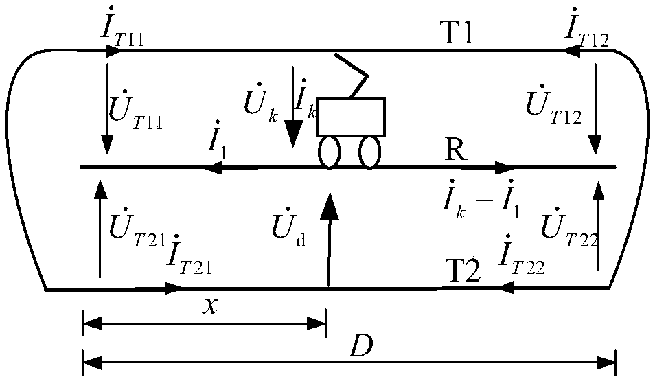
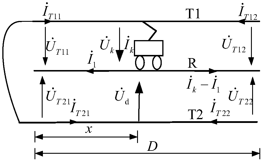
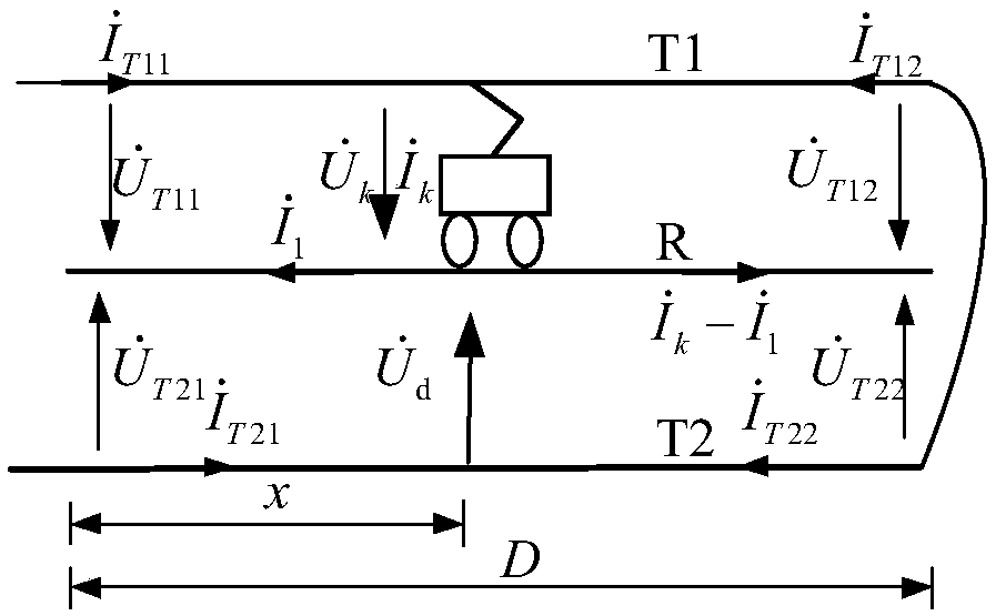
[0029] like figure 1 As shown, assume that the segment length of the electrified railway direct-supply traction network is D, the head and the end of the uplink and downlink contact lines are connected in parallel, and the self-impedance of the uplink contact line T1 and the downlink contact line T2 is both Z T , the self-impedance of rail R is Z R , the mutual impedance between the uplink contact line T1 and the downlink contact line T2 is Z TT ;Synchronously measure the voltage phasor and current phasor at both ends of each segment of the direct supply traction network, including the voltage phasor at the head end of the uplink contact line T1 and head current phasor terminal voltage phasor and terminal current phasor Voltage phasor at the head end of downlink contact line T2 and head current phasor terminal voltage phasor and terminal current phasor Assume that the current is taken at a distance of x km from the head end of the section of the direct supply t...


PUM


Abstract

The invention discloses an uplink and downlink overhead contact line equipment parallel state identification method of a direct feeding traction network, wherein the method belongs to the field of electric railway power supplying technology. Through synchronously measuring a head-end voltage vector and a head-end current vector and a tail-end voltage vector of each segmented contact line of the traction network, a circuit equation is written and a current acquisition position x is solved. When the voltage above two ends of the segment of the direct feeding traction network is in a normal rangeabove 19kV, the formula is used for calculating the current acquisition position x. Through comparing each formula calculating result, a head-end or tail-end parallel condition of each segment of thedirect feeding traction network is determined in an online manner, and the head-end or tail-end parallel conditions comprises four conditions of 1, head-end and tail-end parallel connection; 2, head-end parallel connection and tail-end no parallel connection; 3, head-end no parallel connection and tail-end parallel connection; and 4, head-end and tail-end no parallel connection. The method has advantages of performing identification and early-warning on the operation condition of the direct feeding overhead contact line equipment, realizing real-time monitoring and feedback to the condition change of the traction network, and improving automation level and intelligence level in operation and management of the traction network. Furthermore the method has advantages of high versatility andeasy application.

Description

technical field [0001] The invention relates to the technical field of electric railway traction power supply. Background technique [0002] my country's railway construction has attracted worldwide attention and achieved remarkable results. As of 2017, the operating mileage of my country's railways has reached 127,000 km, of which the operating mileage of high-speed railways has increased to 25,000 km. High-speed railways generally use AT (Auto Transformer, autotransformer) power supply mode, but a large number of normal-speed railways and freight lines still use DT (direct power supply) mode, and the safety and good operation of traction power supply systems must be highly valued. [0003] The traction net has no backup and is exposed to nature. In addition, the pantograph-catenary contact at high speed will easily lead to various faults. In order to isolate the fault as much as possible, reduce the scope of the fault, and save the time for fault finding, the catenary can...

Claims


Application Information

Patent Timeline
IPC IPC(8): G01R31/08
CPCG01R31/086
Inventor 周志成李群湛关达易东崔耀林马庆安刘朝晖陈民武代富强解绍锋杨乃琪
Owner SHENHUA BAOSHEN RAILWAY GRP
Why Eureka
Try Eureka