Intraocular lens injection device

A technology of intraocular lens and injection device, which is applied in the field of intraocular lens implantation surgical instruments, can solve problems such as slot damage, inconvenient bolus injection process, and inability to fix the crystal clip, so as to realize bolus injection speed and bolus injection force, and greatly economical Benefits, the effect of achieving standardization

Active Publication Date: 2021-01-15
LIAONING MEILIN PHARMA
View PDF2 Cites 1 Cited by
  • Summary
  • Abstract
  • Description
  • Claims
  • Application Information

AI Technical Summary

Problems solved by technology

[0007] Chinese patent (Application No. 201310284537.0) discloses an intraocular lens implanter. The injection chamber of the intraocular lens implanter is arranged in the opening groove at the front end of the shell to prevent the injection chamber from turning left and right, and during the injection process The thrust is buffered to reduce the damage and pull of the posterior haptics. However, the injection head (crystal clip) of the implanter is stuck in the opening groove of the shell. When the injection head (crystal clip) is placed on the shell, if If the thrust is too large, the opening slot will be easily damaged, the crystal clip cannot be fixed, and the back and forth shaking will bring inconvenience to the crystal injection process; Chinese patent (application number 201520676150.4) discloses an artificial crystal injector, the injector housing The front end near the end is provided with a card slot for installing and fixing the crystal clip, which can fix the crystal clip. However, when the crystal clip is connected to the housing through the card slot, if the force is too large, the card slot will be damaged, which is not convenient for the crystal. Bolus process
[0009] In summary, there is currently no IOL implanter that can change the combined installation of the injector and the lens clip, reduce the risk of damage to the intraocular lens, and realize the replacement of the lens clip and the secondary use of the injector. A device that can provide practice bolus advance speed and angle control for interns or medical students

Method used


Image

  • Intraocular lens injection device
  • Intraocular lens injection device
  • Intraocular lens injection device

Examples


Embodiment Construction

[0042] The present invention is described in further detail now in conjunction with accompanying drawing. These drawings are all simplified schematic diagrams, which only illustrate the basic structure of the present invention in a schematic manner, so they only show the configurations related to the present invention.

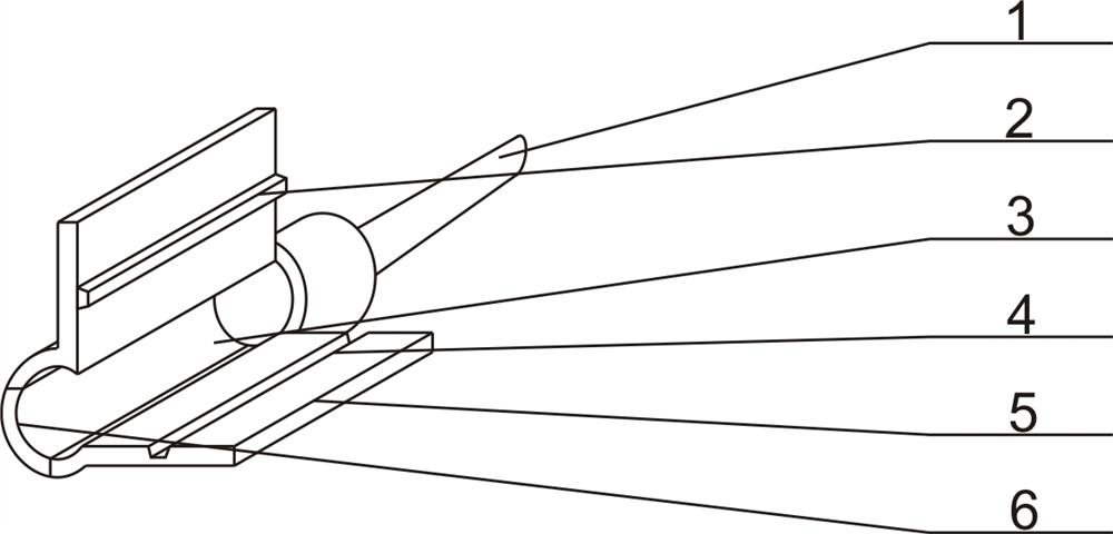
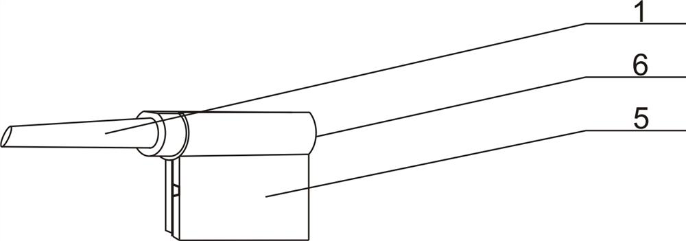
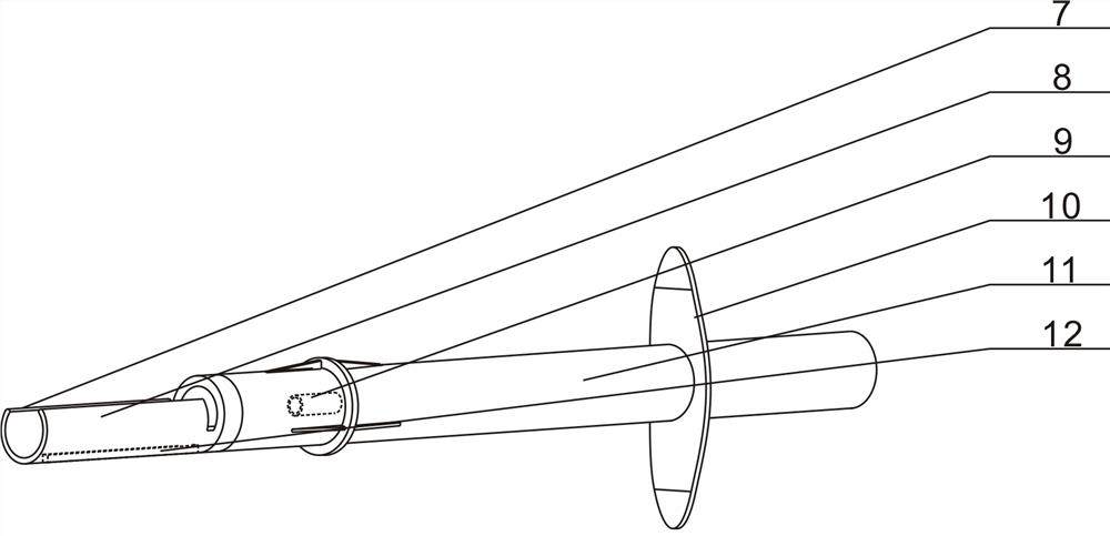
[0043] combined with Figure 1-14In the intraocular lens injection device provided, the injection device includes a folding folder 6, a needle tube 11 and a push rod 64, and the folding folder 6 is composed of a tip 1, a crystal storage tube 3 and two movable pieces 5. One side of the tube 3 is provided with a second opening, a movable piece 5 is respectively arranged on the left and right sides of the second opening on the side of the storage tube 3, and a movable piece 5 is arranged on the inner surface of the left side of the second opening. There is a raised guide groove 4, and a concave guide corresponding to the raised guide groove 4 on the inner surfac...


PUM


Abstract

The invention discloses an artificial lens pushing and injecting device, and relates to an artificial lens implantation surgical operation instrument. Two moving pieces which can be opened and closedare arranged on a folding clamp, an annular groove which fits the folding clamp is formed in the front end of a needle tube, and a push rod is arranged in the needle tube. According to the device, a traditional combined installing manner of the folding clamp and an injector is changed to reduce the risk of the damage of an artificial lens and achieve the dismantling and replacing of the folding clamp, recycling of the injector is further achieved, waste is reduced and the medical cost is reduced, accurate practicing and handling of the injection angle and pushing strength of the injector whenartificial lens injection operation can be performed aiming at an interned doctor or a student of a medical school, the standardized and normalized of artificial lens implantation operation operatingprocedures are achieved, and operation medical risk is greatly reduced.

Description

technical field [0001] The invention relates to an intraocular lens implantation surgical instrument, in particular to an intraocular lens injection device. Background technique [0002] It is well known that the intraocular lens is currently the most effective method for correcting the refraction of aphakic eyes. It replaces the original lens anatomically and optically, and constitutes a nearly normal system, especially the one fixed in the normal physiological position of the lens. Posterior chamber intraocular lens. It can be used for one eye, and the visual acuity can be restored quickly after operation, and it is easy to establish binocular monovision and stereopsis. According to the different materials of IOLs, IOLs are divided into hard IOLs formed of hard materials and soft IOLs. Soft IOLs are also called foldable IOLs. When using a rigid IOL, the surgical incision should be at least 6 mm wide at the time of implantation. In contrast, intraocular lenses made of so...

Claims


Application Information

Patent Timeline
Patent Type & Authority Patents(China)
IPC IPC(8): A61F2/16
CPCA61F2/1664A61F2/1667
Inventor 娄飞齐琦贾盼盼李丽于越代颖刘宇王素梅
Owner LIAONING MEILIN PHARMA
Why Eureka
Try Eureka