A fast flocculator used in a catalytic cracking oil slurry settling tank and its manufacturing method
A technology of catalytic cracking oil slurry and flocculator, which is applied in chemical instruments and methods, settling tanks, separation methods, etc., to achieve the effect of improving the effect of sedimentation and separation, reducing investment and improving economic benefits
- Summary
- Abstract
- Description
- Claims
- Application Information
AI Technical Summary
Problems solved by technology
Method used
Image
Examples
Embodiment 1
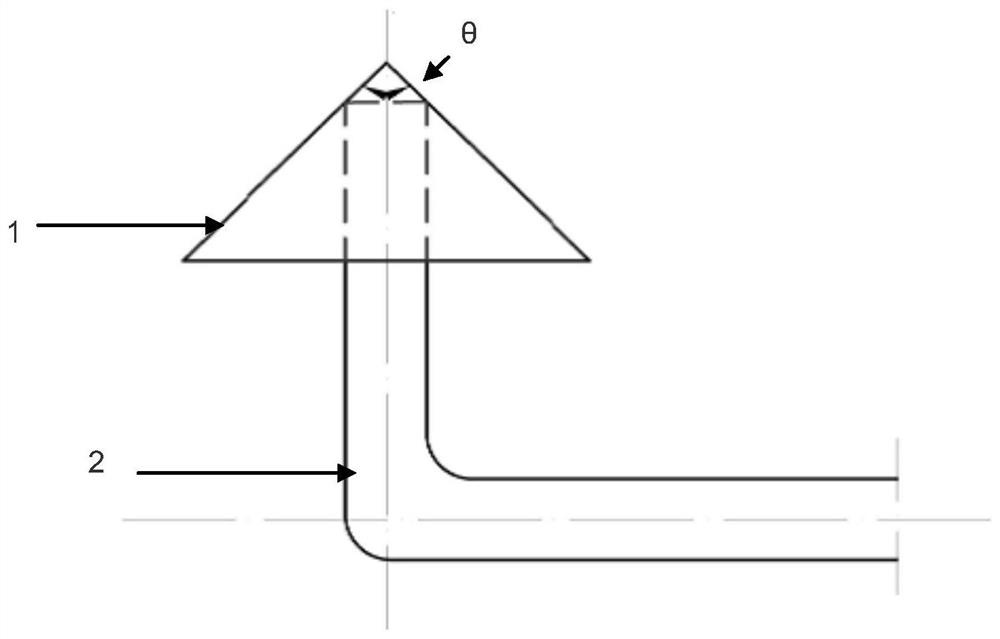
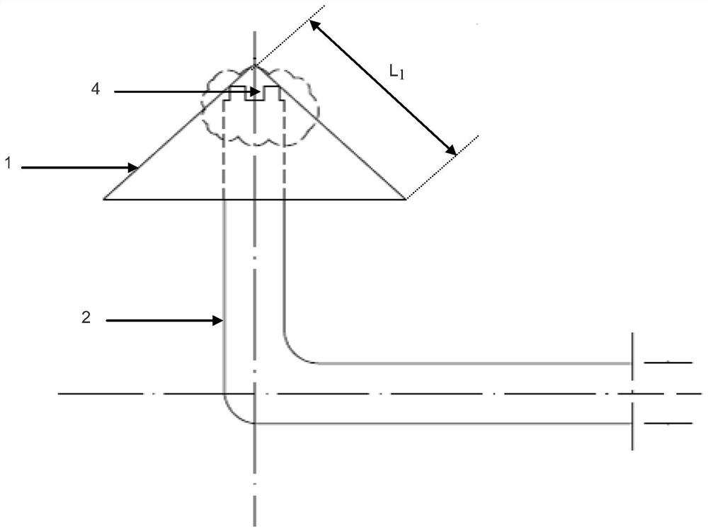
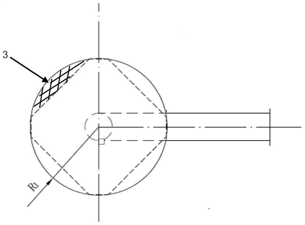
[0094] Such as Figure 1-5 As shown, this embodiment provides a fast flocculator for use in a sedimentation tank of a catalytic cracking oil slurry, which includes a working cavity (that is, the flocculator body) and a draft tube 2. The working cavity is a hollow cone 1, so The cone 1 includes a side panel and a bottom panel. A number of notches are cut along the edge of the bottom panel as the flocculator discharge port 3, and a circular hole is cut with the center of the bottom panel as the guide tube insertion port. The draft tube 2 is a hollow pipe. The tail end of the tube is cut with a number of grooves along the pipe wall. The tail end of the draft tube 1 passes through the draft tube insertion port and is welded to the inner wall of the side panel. The groove is at the top of the inner side of the cone 1 and serves as the flocculator feed port 4.
[0095] Preferably, the axial section of the cone 1 is an isosceles triangle with a top angle θ of 90°, and the included angl...
Embodiment 2
[0102] This example provides a set of basic parameters for designing the fast flocculator in the FCC slurry sedimentation tank:
[0103] A. Residence time, the residence time T of the oil slurry in the working cavity is 3-10 seconds, preferably 5 seconds;
[0104] B. The feed flow rate of the flocculator, the flow rate of the oil slurry into the flocculator v 1 Use 1-2.5 m / s, preferably 1 m / s;
[0105] C. The flow rate of the flocculator, the flow rate of the oil slurry out of the flocculator v 2 1-3.5 m / sec, preferably 2.5 m / sec;
[0106] D. The treatment capacity of the flocculator, the treatment capacity Q under actual application conditions, the unit is meter 3 / second.
[0107] Where T, v 1 , V 2 In specific applications, it is pre-selected according to actual working conditions and requirements, and Q is the processing capacity under actual working conditions.
Embodiment 3
[0109] On the basis of the combination of Examples 1 and 2, the present invention also provides a method for manufacturing a fast flocculator used in a settling tank of a catalytic cracking oil slurry:
[0110] Step 1. Calculate the overall dimensions of the flocculator: Based on the treatment capacity Q and the residence time T of the flocculator, calculate the bus length L of the cone 1 And the radius of the bottom panel R 1 .
[0111] Step 2: Calculate the flow area of the flocculator's feed inlet: the flow area of the flocculator's feed inlet is the flow area of the draft tube oil slurry into the working chamber, and the flocculator's feed flow rate v 1 And the flocculator's processing capacity Q is calculated based on the flow area S of the flocculator inlet 1 .
[0112] Step 3. Calculate the flow area of the flocculator outlet: the flow area of the flocculator outlet is the flow area of the oil slurry in the working chamber entering the settling tank, and the flow ra...
PUM
| Property | Measurement | Unit |
|---|---|---|
| thickness | aaaaa | aaaaa |
| thickness | aaaaa | aaaaa |
Abstract
Description
Claims
Application Information
 - R&D
- Intellectual Property
- Life Sciences
- Materials
- Tech Scout
- Unparalleled Data Quality
- Higher Quality Content
- 60% Fewer Hallucinations
Browse by: Latest US Patents, China's latest patents, Technical Efficacy Thesaurus, Application Domain, Technology Topic, Popular Technical Reports.
© 2025 PatSnap. All rights reserved.Legal|Privacy policy|Modern Slavery Act Transparency Statement|Sitemap|About US| Contact US: help@patsnap.com


