

Novel bearing cleaning device
A new type of bearing cleaning technology, applied in cleaning methods and utensils, cleaning methods using tools, cleaning methods using liquids, etc., can solve the problems of difficult to remove impurities, insufficient bearing cleaning, poor cleaning effect, etc. The effect of convenience, reduced collision, and convenient operation
- Summary
- Abstract
- Description
- Claims
- Application Information
AI Technical Summary
Problems solved by technology
Method used
Image

Examples
Embodiment Construction
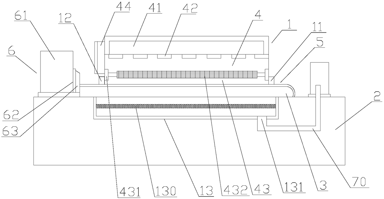
[0018] refer to figure 1 , 2 And 3, a novel bearing cleaning device of the present invention comprises a cleaning box 1, a frame 2, a conveyor belt 3, a cleaning mechanism 4, a bearing fixing mechanism 5, and a discharge box 6, and the cleaning box 1 is installed on the frame 2, The front and rear sides of the cleaning box 1 are respectively provided with a cleaning box inlet 11 and a cleaning box outlet 12, the conveyor belt 3 is arranged through the cleaning box 1, and the two ends of the conveyor belt 3 extend to the cleaning box inlet 11 and the cleaning box outlet 12 respectively. In addition, the conveyor belt 3 is provided with a bearing fixing mechanism 5, and the front end of the cleaning box outlet 12 is provided with a discharge box 6, and the cleaning mechanism 4 includes a water tank 41, several spray heads 42, brush devices 43 and control device 44, the water tank 41 is installed above the inside of the cleaning tank 1, the shower head 42 is arranged at the bott...
PUM
 Abstract
Description
Claims
Application Information