Wafer cutting equipment

A technology for cutting equipment and wafers, applied in stone processing equipment, work accessories, fine work devices, etc., can solve the problems of low work efficiency, low recycling rate, poor powder cleaning effect, etc., to improve the filtering effect, improve the The effect of filtration efficiency

Pending Publication Date: 2018-11-23
江苏英锐半导体有限公司
View PDF0 Cites 3 Cited by
  • Summary
  • Abstract
  • Description
  • Claims
  • Application Information

AI Technical Summary

Problems solved by technology

[0002] As we all know, wafer cutting equipment is an auxiliary equipment for cutting wafers of different sizes, which has been widely used in the field of semiconductor manufacturing; existing wafer cutting equipment includes cutting tables, clamping mechanisms, The exhaust fan and the operating mechanism, the clamping mechanism and the operating mechanism are all installed on the top side wall of the cutting table, a first exhaust pipe is arranged above the cutting table, and an exhaust fan is arranged at the output end of the first exhaust pipe; the existing wafer When the cutting equipment is in use, the user places the input end of the first exhaust pipe above the cutting table, uses the clamping mechanism to clamp the wafer to be cut, and then controls the cutting equipment to cut through the operating mechanism, and the user connects the exhaust fan to the outside world. Power connection, under the action of suction of the exhaust fan, the powder generated during cutting is drawn out along the first exhaust pipe; in the use of existing wafer cutting equipment, it is found that the cleaning effect of the powder generated during cutting is poor, and the recycling rate is low. Low; the clamping mechanism cannot rotate with the user's movement, and the use limitations are high; the operating mechanism is difficult to rotate, the operating speed is slow, and the work efficiency is low

Method used


Image

  • Wafer cutting equipment
  • Wafer cutting equipment
  • Wafer cutting equipment

Examples


Embodiment Construction

[0019]The specific implementation manners of the present invention will be further described in detail below in conjunction with the accompanying drawings and embodiments. The following examples are used to illustrate the present invention, but are not intended to limit the scope of the present invention.

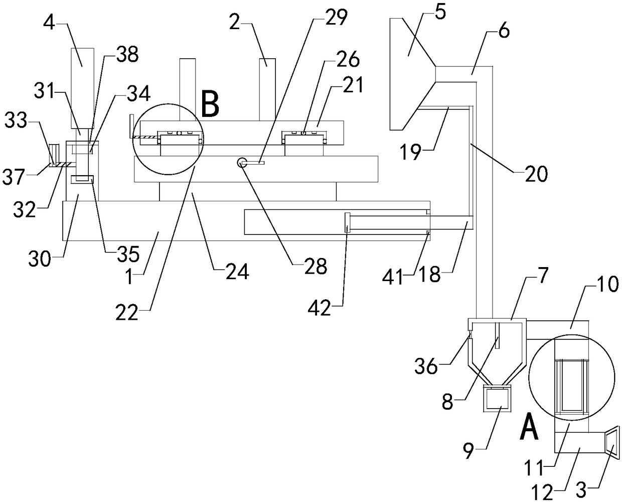
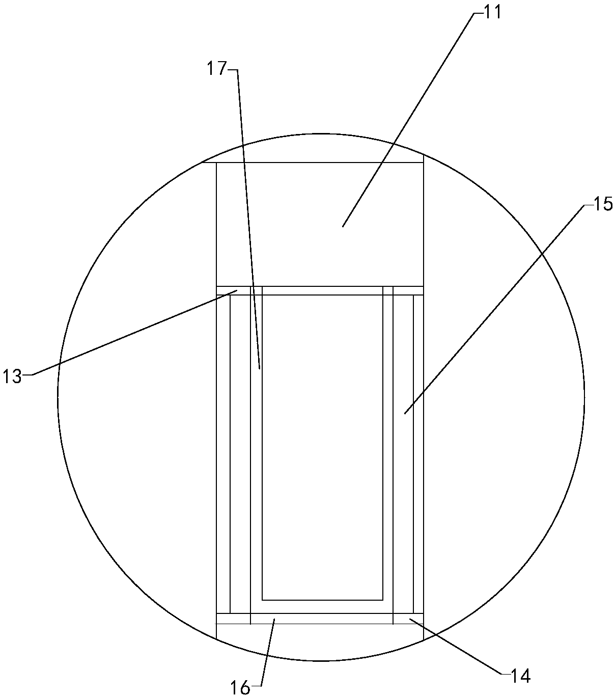
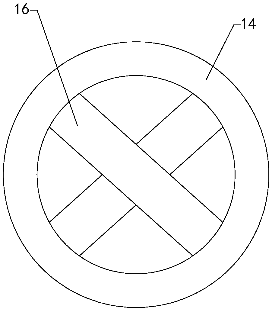
[0020] Such as Figure 1 to Figure 5 As shown, a wafer cutting device of the present invention includes a cutting table 1, a clamping mechanism 2, an exhaust fan 3 and an operating mechanism 4, and a first exhaust pipe 5 is arranged above the cutting table; it also includes a conical collection cover 6 , Gravity dust removal box 7, baffle plate 8, gathering groove 9, second exhaust duct 10, transition duct 11, third exhaust duct 12, upper fixing ring 13, lower fixing ring 14, a set of upper support rods 15, A group of lower support rods 16, filter cloth bags 17, pull rods 18, first connecting rods 19 and second connecting rods 20, a collection hole is arranged in the centr...


PUM


Abstract

The invention relates to the technical field of semiconductor manufacturing accessory devices, in particular to wafer cutting equipment which can enhance the powder cleaning effect; a user can use thewafer cutting equipment conveniently; the operation speed is improved; the wafer cutting equipment comprises a cutting table, a clamping mechanism, an exhaust fan and an operation mechanism, whereina first exhaust pipe is arranged above the cutting table; the wafer cutting equipment further comprises a tapered collecting shield, a gravity dust removing box, a flow stopping plate, a gathering groove, a second exhaust pipe, a transition pipe, a third exhaust pipe, an upper fixing ring, a lower fixing ring, one set of upper supporting rods, one set of lower supporting rods, a filter cloth bag,a withdrawing rod, a first connection rod and a second connection rod; and the wafer cutting equipment further comprises an upper base, a lower base, one set of upper sliding blocks, one set of lowersliding blocks, one set of upper rolling beads, one set of lower rolling beads, an upper threaded rod, a lower threaded rod, one set of handles, a limiting rod, a rotary rod, a left threaded rod and alengthening rod.

Description

technical field [0001] The invention relates to the technical field of semiconductor manufacturing auxiliary devices, in particular to a wafer cutting device. Background technique [0002] As we all know, wafer cutting equipment is an auxiliary equipment for cutting wafers of different sizes, which has been widely used in the field of semiconductor manufacturing; existing wafer cutting equipment includes cutting tables, clamping mechanisms, The exhaust fan and the operating mechanism, the clamping mechanism and the operating mechanism are all installed on the top side wall of the cutting table, a first exhaust pipe is arranged above the cutting table, and an exhaust fan is arranged at the output end of the first exhaust pipe; the existing wafer When the cutting equipment is in use, the user places the input end of the first exhaust pipe above the cutting table, uses the clamping mechanism to clamp the wafer to be cut, and then controls the cutting equipment to cut through th...

Claims


Application Information

Patent Timeline
Patent Type & Authority Applications(China)
IPC IPC(8): B28D5/00B28D7/02
CPCB28D5/00B28D7/02
Inventor 王昌华
Owner 江苏英锐半导体有限公司
Why Eureka
Try Eureka