Pipe fitting blanking shunt mechanism

A technology of pipe fittings and shunts, applied in conveyors, conveyor objects, transportation and packaging, etc., can solve the problems affecting the shunt transmission of pipe fittings, the limited application scope of shunt transmission of pipe fittings, and the blocking of pipe fittings, and achieve reasonable structural design. , The effect of stable and efficient shunt transmission, stable and orderly feeding

Inactive Publication Date: 2018-11-23
海宁市波菲特进出口有限公司
View PDF0 Cites 1 Cited by
  • Summary
  • Abstract
  • Description
  • Claims
  • Application Information

AI Technical Summary

Problems solved by technology

In the existing automatic production line of pipe fittings, according to the different production efficiency of each process, one feeder is required to supply pipe fittings to multiple processing or assembly machines, and the pipe fittings are sent separately to realize the automatic and efficient transmission and processing of pipe fittings. During the split conveying process of the existing pipe fittings, it is difficult to conveniently and smoothly divide the pipe fittings conveyed by one material pipe into two or more pipes for conveying. Poor, it often causes jamming of pipe fittings in the process of branching transmission of pipe fittings, which affects the normal branch transmission of pipe fittings, and in the process of branch transmission of existing pipe fittings, the conventional branching mechanism can only realize the alternating of pipe fittings It is difficult to select the required material tube for feeding pipe fittings according to the needs of specific processing and use. The application range of pipe fittings shunting transmission is limited and cannot meet the needs of processing and use.

Method used


Image

  • Pipe fitting blanking shunt mechanism
  • Pipe fitting blanking shunt mechanism
  • Pipe fitting blanking shunt mechanism

Examples


Embodiment Construction

[0014] In order to further describe the present invention, a specific implementation of a pipe fitting unloading and branching mechanism will be further described below in conjunction with the accompanying drawings. The following examples are explanations of the present invention and the present invention is not limited to the following examples.

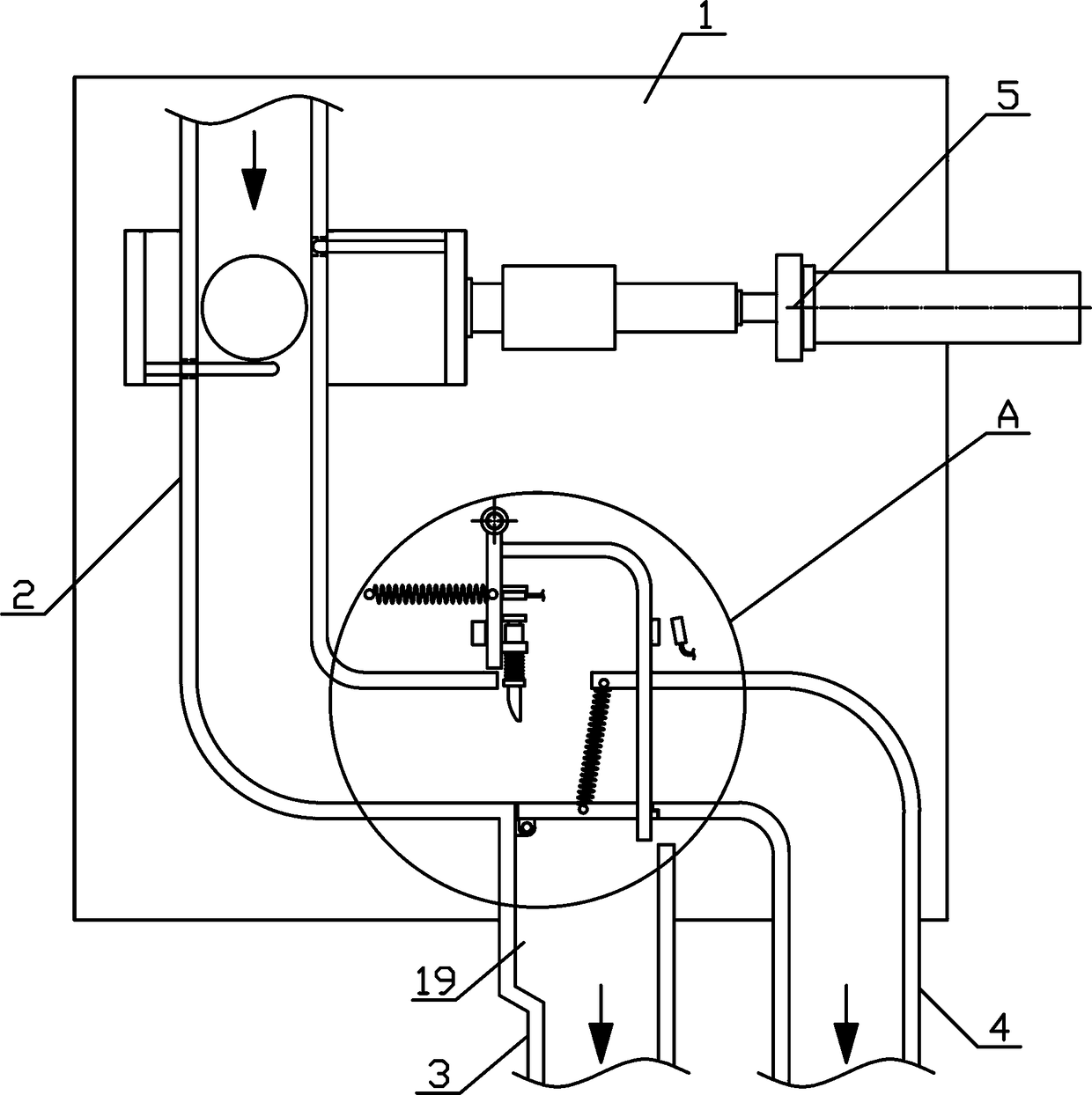
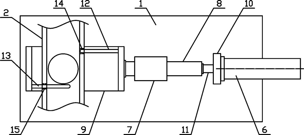
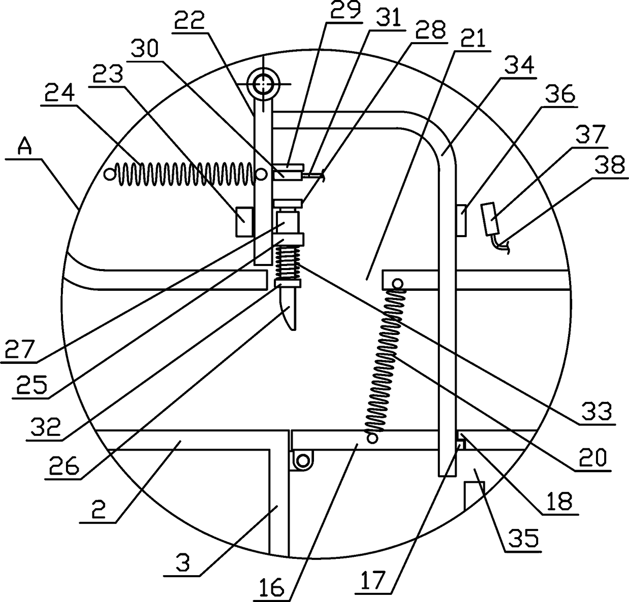
[0015] Such as figure 1 As shown, a pipe fitting blanking and shunting mechanism of the present invention includes a fixed bracket 1, a feeding material pipe 2, a front shunting material pipe 3, a rear shunting material pipe 4 and a material separation mechanism 5, and the feeding material pipe 2 is vertical It is arranged directly on one side of the fixed bracket 1, and the feeding material pipe 2 is an L-shaped structure. The middle part of the lower side of 2 is connected, the rear branch material pipe 4 is vertically arranged at the lower end of the feed material pipe 2, the upper end of the rear branch material pipe 4 is connec...


PUM


Abstract

The invention discloses a pipe fitting blanking shunt mechanism, which belongs to the machinery equipment field of workpiece processing and conveying. The pipe fitting blanking shunt mechanism comprises a fixed support, a feeding pipe, a front shunting pipe, a rear shunting pipe and a material separating mechanism. The front shunting pipe is arranged vertically in the middle of the lower side of the feeding pipe, and the rear shunting pipe is arranged vertically at the end of the lower side of the feeding pipe. The material separating mechanism is arranged horizontally on the upper side of thefeeding pipe. The inner sides of a material separating support are horizontally fixed with an upper partition plate and a lower partition plate respectively. The upper end of the front shunting pipeis provided with a rotating baffle. The upper end of a reciprocating rotary plate is hinged to the fixed support, and a lifting bar is vertically and slidably arranged in a rod support. A hook switch board is arranged on one side of the reciprocating rotary plate. The design of the pipe fitting blanking shunt mechanism is reasonable, which can move the pipe piece one by one, carry on the shunt transfer effectively as needed, and automation degree of pipeline transmission can be improved to meet the needs of production and use.

Description

technical field [0001] The invention belongs to the field of workpiece processing and conveying machinery, and in particular relates to a pipe fitting unloading and branching mechanism, which is mainly used in the continuous conveying and processing of pipe fittings. Background technique [0002] Pipe fittings refer to workpieces with a cylindrical structure. There are many types of pipe fittings. Different pipe fittings use different materials. The quality of the material directly determines the quality of the pipe fittings. Pipe fittings are necessary materials for construction engineering and mechanical equipment. A general term for components that play the roles of connection, control, direction change, flow diversion, sealing, support, etc. Steel pipe fittings are the most important type of pipe fittings. Steel pipe fittings are pressure-bearing pipe fittings. According to different processing techniques, steel pipe fittings can be divided into: butt welding pipe fittin...

Claims


Application Information

Patent Timeline
IPC IPC(8): B65G47/04B65G47/88
CPCB65G47/04B65G47/8876B65G2201/0276
Inventor 沈洁
Owner 海宁市波菲特进出口有限公司
Why Eureka
Try Eureka