Directed conveying mechanism for electronic insulating parts

A technology of electronic insulation and conveying mechanism, which is applied to conveyors, conveyor objects, transportation and packaging, etc., can solve the problems of high cost, troublesome production and directional conveying of electronic insulation parts, complicated design of directional conveying mechanism, etc., and achieve low cost. , Simple structure and high reliability

Inactive Publication Date: 2018-11-23
SUZHOU INST OF TRADE & COMMERCE
View PDF3 Cites 9 Cited by
  • Summary
  • Abstract
  • Description
  • Claims
  • Application Information

AI Technical Summary

Problems solved by technology

Electronic insulating parts must not only have good electrical insulation properties, but due to different purposes, objects or occasions, there are specific requirements for electronic insulating parts, materials, dielectric constant, dielectric loss, thermal expansion coefficient, etc., which form a variety of Shaped electronic insulating parts, which brings troubles to the production and directional delivery of electronic insulating parts, which requires the design of complex directional delivery mechanisms and corresponding control devices, and the cost is very high

Method used


Image

  • Directed conveying mechanism for electronic insulating parts

Examples


Embodiment Construction

[0016] The present invention will be described in detail below with reference to the accompanying drawings and in combination with embodiments.

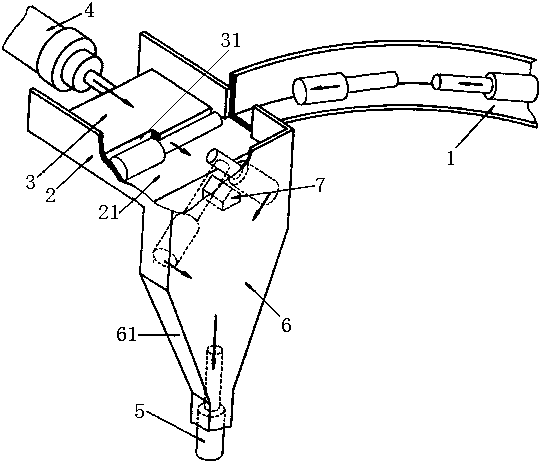
[0017] refer to figure 1 As shown, a directional conveying mechanism for electronic insulating parts includes a feeding conveying track 1 and a stepped electronic insulating part 5 conveyed on the feeding conveying track 1, and the end of the feeding conveying track 1 is connected to There is a push-out groove 2, and a push-out plate 3 is slidably arranged in the push-out groove 2, and one end of the push-out plate 3 is fixedly connected with a cylinder rod of a cylinder 4, and the cylinder rod of the cylinder 4 drives the push-out plate 3 on the flat surface. Slide on the push groove 2, the other end of the push plate 3 is a push chamber 21, and the electronic insulating part 5 on the feed conveying track 1 is transported into the push chamber through the end of the feed conveying track 1 and the push groove 2 21, one side of the p...


PUM


Abstract

The invention discloses a directed conveying mechanism for electronic insulating parts. The directed conveying mechanism comprises a feeding conveying track and the stepped electronic insulating partsconveyed on the feeding conveying track; the tail end of the feeding conveying track is connected with a horizontal pushing groove; a pushing plate is glidingly arranged inside the horizontal pushinggroove; one end of the pushing plate is fixedly connected with a cylinder rod of an air cylinder; a pushing chamber is arranged at the other end of the pushing plate; a directed chamber is verticallyarranged on one side of the pushing chamber; and an inlet of the directed chamber is located on the pushing stroke of the pushing chamber and the pushing plate, so that the electronic insulating parts in the pushing chamber are pushed into the inlet of the directed chamber through the pushing plate, and the electronic insulating parts entering the pushing chamber slide down along the side wall ofthe directed chamber under the effect of gravity. By the aid of the directed conveying mechanism, directed conveyance can be performed on the stepped electronic insulating part structures, overturning and directing of the electronic insulating parts can be realized by the aid of the gravity and the conveying structure, no complex control system is required, the structure is simple, the cost is low, and the reliability is high.

Description

technical field [0001] The invention relates to the technical field of electronic equipment, in particular to a directional conveying mechanism for electronic insulating parts. Background technique [0002] Electronic insulating parts in the electronics industry, including packaging materials for electronic devices, circuit board materials, insulating silicone grease and insulating rubber drilling agents, etc. Electronic insulating parts must not only have good electrical insulation properties, but due to different purposes, objects or occasions, there are specific requirements for electronic insulating parts, materials, dielectric constant, dielectric loss, thermal expansion coefficient, etc., which form a variety of Shaped electronic insulating parts, which brings troubles to the production and directional delivery of electronic insulating parts, which requires the design of complex directional delivery mechanisms and corresponding control devices, and the cost is very hig...

Claims


Application Information

Patent Timeline
Patent Type & Authority Applications(China)
IPC IPC(8): B65G47/248
CPCB65G47/248B65G2201/02
Inventor 武艳
Owner SUZHOU INST OF TRADE & COMMERCE
Why Eureka
Try Eureka