Rotor system and control method of rotor system as well as gas turbine generator set and control method of gas turbine generator set
What is AI technical title?
AI technical title is built by Patsnap AI team. It summarizes the technical point description of the patent document.
A rotor and compressor technology, applied in gas turbine devices, machines/engines, mechanical equipment, etc.
Pending Publication Date: 2018-11-23
刘慕华
View PDF5 Cites 16 Cited by
Summary
Abstract
Description
Claims
Application Information
AI Technical Summary
This helps you quickly interpret patents by identifying the three key elements:
Problems solved by technology
Method used
Benefits of technology
Problems solved by technology
[0005] The present invention provides a rotor system and its control method, a gas turbine generator set and its control method, so as to solve the above-mentioned problems existing in the existing gas turbine generator set
Method used
Image
Click on the blue label to locate the original text in one second.
Reading with bidirectional positioning of images and text.
Examples
Embodiment 1
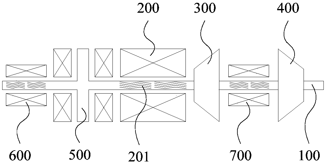
[0188] Such as Figure 1 to Figure 3 As shown, the rotor system includes:
[0189] The rotating shaft 100, the shaft body of the rotating shaft 100 has an integrated structure, and the rotating shaft 100 is arranged horizontally;
[0190] The motor 200, the compressor 300 and the turbine 400 are sequentially arranged on the rotating shaft 100;
[0191] And, the thrust bearing 500, the first radial bearing 600 and the second radial bearing 700 arranged on the rotating shaft 100, the first radial bearing 600 is arranged on the side of the motor 200 away from the compressor 300, the second radial bearing 700 is provided between the compressor 300 and the turbine 400 .
[0192] The thrust bearing 500 is arranged between the first radial bearing 600 and the motor 200, such as figure 1 shown; or, the thrust bearing 500 is arranged on the side of the first radial bearing 600 away from the motor 200, as figure 2 shown; or, the thrust bearing 500 is arranged between the motor 200 ...
Embodiment 2
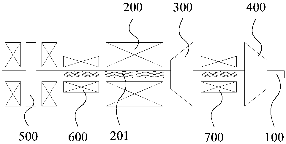
[0206] Such as Figure 7 to Figure 10 As shown, the rotor system includes:
[0207] The rotating shaft 100, the shaft body of the rotating shaft 100 has an integrated structure, and the rotating shaft 100 is arranged horizontally;
[0208] The motor 200, the compressor 300 and the turbine 400 are sequentially arranged on the rotating shaft 100;
[0209] And, the thrust bearing 500, the first radial bearing 600, the second radial bearing 700 and the third radial bearing 800 arranged on the rotating shaft 100, the first radial bearing 600 is arranged on a side of the motor 200 away from the compressor 300 On the side, the second radial bearing 700 is arranged between the compressor 300 and the turbine 400 , and the third radial bearing 800 is arranged between the motor 200 and the compressor 300 .
[0210] The thrust bearing 500 is arranged between the first radial bearing 600 and the motor 200, such as Figure 7 shown; or, the thrust bearing 500 is arranged on the side of th...
Embodiment 3
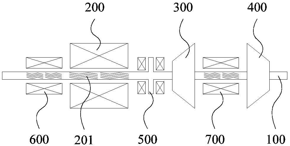
[0219] Such as Figure 15 As shown, the rotor system includes:
[0220] The rotating shaft 100, the shaft body of the rotating shaft 100 has an integrated structure, and the rotating shaft 100 is arranged horizontally;
[0221] The motor 200, the compressor 300 and the turbine 400 are sequentially arranged on the rotating shaft 100;
[0222] And, the thrust bearing 500, the first radial bearing 600, the second radial bearing 700 and the fourth radial bearing 900 arranged on the rotating shaft 100, the first radial bearing 600 is arranged on a side of the motor 200 away from the compressor 300 side, the second radial bearing 700 is arranged between the compressor 300 and the turbine 400, the fourth radial bearing 900 is arranged on the side of the turbine 400 away from the compressor 300, and the thrust bearing 500 is arranged between the compressor 300 and the first between the two radial bearings 700 .
[0223] The embodiment of the present invention can be applied to the ...
PUM
Abstract
The invention provides a rotor system and a control method of the rotor system as well as a gas turbine generator set and a control method of the gas turbine generator set. The rotor system comprisesa rotating shaft, a generator, a gas compressor and a turbine as well as a thrust bearing and at least two radical bearings, wherein a shaft body of the rotating shaft is of an integrated structure and is horizontally arranged, the generator, the gas compressor and the turbine are sequentially arranged on the rotating shaft, the thrust bearing and the radial bearings are arranged on the rotating shaft, the thrust bearing and the radial bearings are non-contact bearings, and the thrust bearing is arranged at the position where the gravity center of the rotor system can be located between two radial bearings which are spaced by the largest distance. According to the rotator system, the shaft body of the rotating shaft in the rotor system is arranged into the integrated structure, so that theproblem that the installation position of a gas-magnetic hybrid thrust bearing is limited due to the fact that a coupling is used for connection in an existing gas turbine generator set is solved; and the arrangement position of the thrust bearing is adjusted, so that the gravity center of the whole rotator system is located between the two radial bearings which are arranged at the farthest distance, and the structure can be kept stable when the whole rotor system rotates at a high speed.
Description
technical field [0001] The invention relates to the technical field of rotors, in particular to a rotor system and a control method thereof, a gas turbine generator set and a control method thereof. Background technique [0002] A gas turbine mainly includes three major components: a compressor, a combustor, and a turbine. After the air enters the compressor, it is compressed into high-temperature and high-pressure air, and then supplied to the combustion chamber for mixed combustion with fuel, and the high-temperature and high-pressure gas generated expands in the turbine to perform work. When the rotor rotates at high speed, the rotor will be subjected to radial force and axial force. In order to limit the radial and axial movement of the rotating shaft, radial bearings and thrust bearings need to be installed in the rotor system. Traditional radial bearings and thrust bearings are common contact bearings. As the rotor speed increases, especially when the rotor speed exc...
Claims
Application Information
Patent Timeline
Application Date:The date an application was filed.
Publication Date:The date a patent or application was officially published.
First Publication Date:The earliest publication date of a patent with the same application number.
Issue Date:Publication date of the patent grant document.
PCT Entry Date:The Entry date of PCT National Phase.
Estimated Expiry Date:The statutory expiry date of a patent right according to the Patent Law, and it is the longest term of protection that the patent right can achieve without the termination of the patent right due to other reasons(Term extension factor has been taken into account ).
Invalid Date:Actual expiry date is based on effective date or publication date of legal transaction data of invalid patent.

