Mixed flow pump impeller structure for reducing cavitation erosion of blade rims

A technology of vane rim and mixed-flow pump, which is applied to components, pumps, and pump components of pumping devices for elastic fluids, and can solve problems such as hydraulic loss, decline in hydraulic performance, and insignificant improvement in pump cavitation performance. , to reduce costs, improve cavitation damage and prolong service life

Active Publication Date: 2018-11-23
JIANGSU UNIV
View PDF8 Cites 6 Cited by
  • Summary
  • Abstract
  • Description
  • Claims
  • Application Information

AI Technical Summary

Problems solved by technology

However, the impeller only moves the flow separation point backward, and the blade cavitation area only moves to the rear of the impeller, which does not significantly improve the cavitation performance of the pump.
Patent CN204610363U welds a chord strip with a widt...

Method used


Image

  • Mixed flow pump impeller structure for reducing cavitation erosion of blade rims
  • Mixed flow pump impeller structure for reducing cavitation erosion of blade rims
  • Mixed flow pump impeller structure for reducing cavitation erosion of blade rims

Examples


Embodiment Construction

[0023] The present invention will be further described below in conjunction with the accompanying drawings and specific embodiments, but the protection scope of the present invention is not limited thereto.

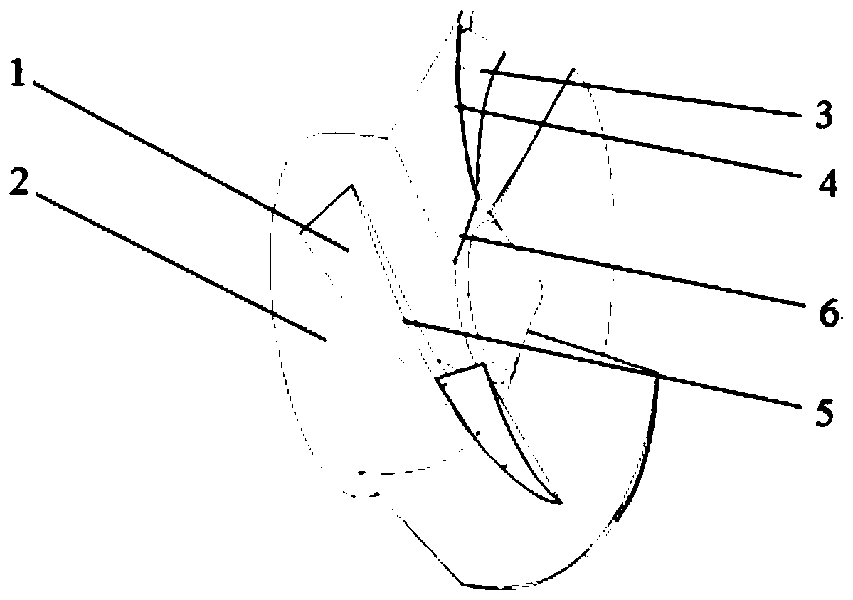
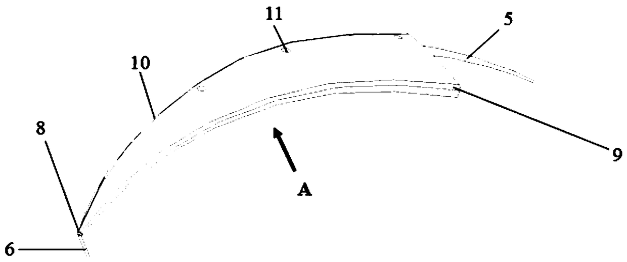
[0024] like figure 1 As shown, the mixed-flow pump impeller structure for improving blade rim cavitation according to the present invention includes a blade 1 , an impeller hub 2 , and a rim drain piece 3 . The blade 1 is installed on the hub 2 of the impeller, and the rim guide piece 3 is installed on the rim 5 of the blade and is located on the side of the inlet edge 6 of the blade.

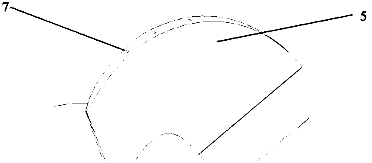
[0025] Specifically, the rim baffle 3 is mounted on the blade rim 5 through set screws 11 . The blade rim 5 is provided with a threaded hole 7 for installing the rim drain piece 3, and the inner diameter of the threaded hole 7 is smaller than the thickness of the blade at the position, such as figure 2 shown. The rim drain piece 3 is drilled with a counterbore 4 for fixing the rim drai...


PUM


Abstract

The invention provides a mixed flow pump impeller structure for reducing the cavitation erosion of blade rims. The mixed flow pump impeller structure comprises blades, an impeller hub and rim drainagepieces, wherein the blades are arranged on the impeller hub, and the rim drainage pieces are arranged on the blade rims and are located on one sides, where the inlet edges are located, of the blades.According to the mixed flow pump impeller structure, the rim drainage pieces are installed at the blade rims, so that bubbles generated by gap blowing-up vortexes of the blade rims are effectively isolated, moreover, bubbles generated by leakage vortex cavitation are killed in the areas away from the surfaces of the blades, then the cavitation erosion damage to the blade rims is reduced, and theservice life of an impeller is prolonged; and the rim drainage pieces are fixed at the blade rims through fastening screws, so that after the rim drainage pieces are damaged due to the cavitation erosion, the method that the rim drainage pieces are directly replaced can be also adopted, the whole impeller is not required to be disassembled, and then the whole life cycle cost is reduced.

Description

technical field [0001] The invention belongs to the technical field of fluid machinery, and in particular relates to a mixed-flow pump impeller structure for improving blade rim cavitation. Background technique [0002] Mixed flow pump is a kind of hydraulic machinery with performance and structure between centrifugal pump and axial flow pump. It has the advantages of large flow, high efficiency and strong cavitation resistance. It is used in agricultural drainage, urban water supply and drainage, large water conservancy projects and nuclear power plants. Areas such as circulating water systems play an important role. Due to the special structure of the mixed flow pump, there is a gap between the rim of the impeller blade and the end wall of the runner chamber. During the rotation of the impeller, due to the large pressure difference between the pressure surface and the suction surface of the blade, the gap is prone to leakage flow, and Leakage flow and mainstream entrainme...

Claims


Application Information

Patent Timeline
IPC IPC(8): F04D29/18F04D29/02F04D29/66
CPCF04D29/026F04D29/18F04D29/669
Inventor 李伟季磊磊施卫东周岭蒋小平朱勇平元峰李恩达马凌凌
Owner JIANGSU UNIV
Why Eureka
Try Eureka