Electric railway AT traction network AT section fault location method

A technology for electrified railways and positioning methods, which is applied to fault locations, fault detection by conductor type, etc., to achieve high accuracy and good versatility

Active Publication Date: 2018-11-23
SOUTHWEST JIAOTONG UNIV
View PDF4 Cites 11 Cited by
  • Summary
  • Abstract
  • Description
  • Claims
  • Application Information

AI Technical Summary

Problems solved by technology

[0006] The purpose of the present invention is to provide a fault location method for the AT section of the AT traction network of an electrified railway, which can effectively eliminate the influence of factors such as the AT traction network structure, operation mode, and transition resistance, and solve the problem of accurate positioning when a short-circuit fault occurs in the AT traction network technical issues

Method used


Image

  • Electric railway AT traction network AT section fault location method
  • Electric railway AT traction network AT section fault location method
  • Electric railway AT traction network AT section fault location method

Examples


Embodiment Construction

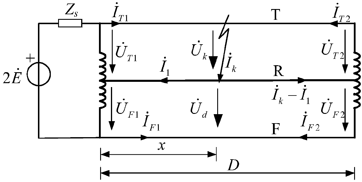
[0024] like figure 1 As shown, let the power supply voltage phasor be The system impedance is Z S , the length of the AT segment of the AT traction network is D, synchronously measure the voltage phasor and current phasor at both ends of the AT segment of the traction network, including the voltage phasor at the head end of the contact line T and the head-end current phasor terminal voltage phasor and terminal current phasors Negative feeder F head-end voltage phasor and the head-end current phasor terminal voltage phasor and terminal current phasors Suppose a TR short circuit occurs at the distance x from the head end of the AT segment (D-x from the short end of the AT) km, write the circuit equation, and solve the fault location:

[0025]

[0026]

[0027] In the formula: the units of length D and x are km, and the units of various impedance Z are Ohm / km; each head-end voltage phasor and terminal voltage phasors The unit is V, each head-end current...


PUM


Abstract

The present invention discloses an electric railway AT (Auto Transformer) traction network AT section fault location method. The voltage phases and the current phases of two ends of a traction networkAT section are measured at the same time, the voltage phases comprise a contact line T head end voltage phase as shown in the description and a head end current phase as shown in the description, a tail end voltage phase as shown in the description and a tail end current phase as shown in the description, and a tail end voltage phase as shown in the description and a tail end current phase as shown in the description, a circuit equation is listed, and a fault position x or D<->x is solved. The method can eliminate the influences of factors such as the structure and the operation mode of the traction network, is suitable for non-metal short-circuit fault condition with large transition resistance, is high in fault location precision, and can be widely suitable for fault location of the electric railway AT traction power supply system.

Description

technical field [0001] The invention relates to the technical field of electric railway traction power supply. Background technique [0002] my country's railway construction has attracted worldwide attention and achieved remarkable results. As of 2017, the operating mileage of my country's railways has reached 127,000 km, of which the operating mileage of high-speed railways has increased to 25,000 km, accounting for two-thirds of the world's total and ranking first in the world. High-speed railways use electric traction without exception. With the increase of high-speed railway mileage, the safety and good operation of the traction power supply system cannot but be highly valued. [0003] AT (Auto Transformer, auto-transformer) power supply mode has the advantages of longer power supply section and greater power supply capacity, which can better meet the requirements of high-speed railway traffic density, high running speed, and large power supply capacity. It is the mai...

Claims


Application Information

Patent Timeline
Patent Type & Authority Applications(China)
IPC IPC(8): G01R31/08
CPCG01R31/086
Inventor 易东李群湛马庆安陈民武赵艺解绍锋杨乃琪
Owner SOUTHWEST JIAOTONG UNIV
Why Eureka
Try Eureka