
Coupled system of optical device and coupled method of optical device

A coupling system and optical device technology, applied in the field of optical device coupling and optical device coupling system, can solve problems such as low coupling efficiency of PD arrays and arrayed waveguide gratings, damage to PD arrays and arrayed waveguide gratings, etc., to prevent being squeezed. The effect of pressure damage, improving packaging yield, and improving coupling efficiency

Pending Publication Date: 2018-11-23
APAT OPTOELECTRONICS COMPONENTS
View PDF14 Cites 10 Cited by
  • Summary
  • Abstract
  • Description
  • Claims
  • Application Information

AI Technical Summary

Problems solved by technology

[0007] The purpose of the present invention is to provide a coupling system for optical devices, aiming at solving the technical problems that the existing coupling system has low coupling efficiency for PD arrays and arrayed waveguide gratings and is easy to cause damage to PD arrays and arrayed waveguide gratings

Method used


Image

  • Coupled system of optical device and coupled method of optical device
  • Coupled system of optical device and coupled method of optical device
  • Coupled system of optical device and coupled method of optical device

Examples


Embodiment Construction

[0055] In order to make the object, technical solution and advantages of the present invention clearer, the present invention will be further described in detail below in conjunction with the accompanying drawings and embodiments. It should be understood that the specific embodiments described here are only used to explain the present invention, not to limit the present invention.

[0056] It should be noted that when a component is referred to as being “fixed on” or “disposed on” another component, it may be directly or indirectly on the other component. When an element is referred to as being "connected to" another element, it can be directly or indirectly connected to the other element. The orientation or positional relationship indicated by the terms "upper", "lower", "left", "right", etc. are based on the orientation or positional relationship shown in the drawings, and are for convenience of description only, rather than indicating or implying the referred device Or ele...


PUM


Abstract

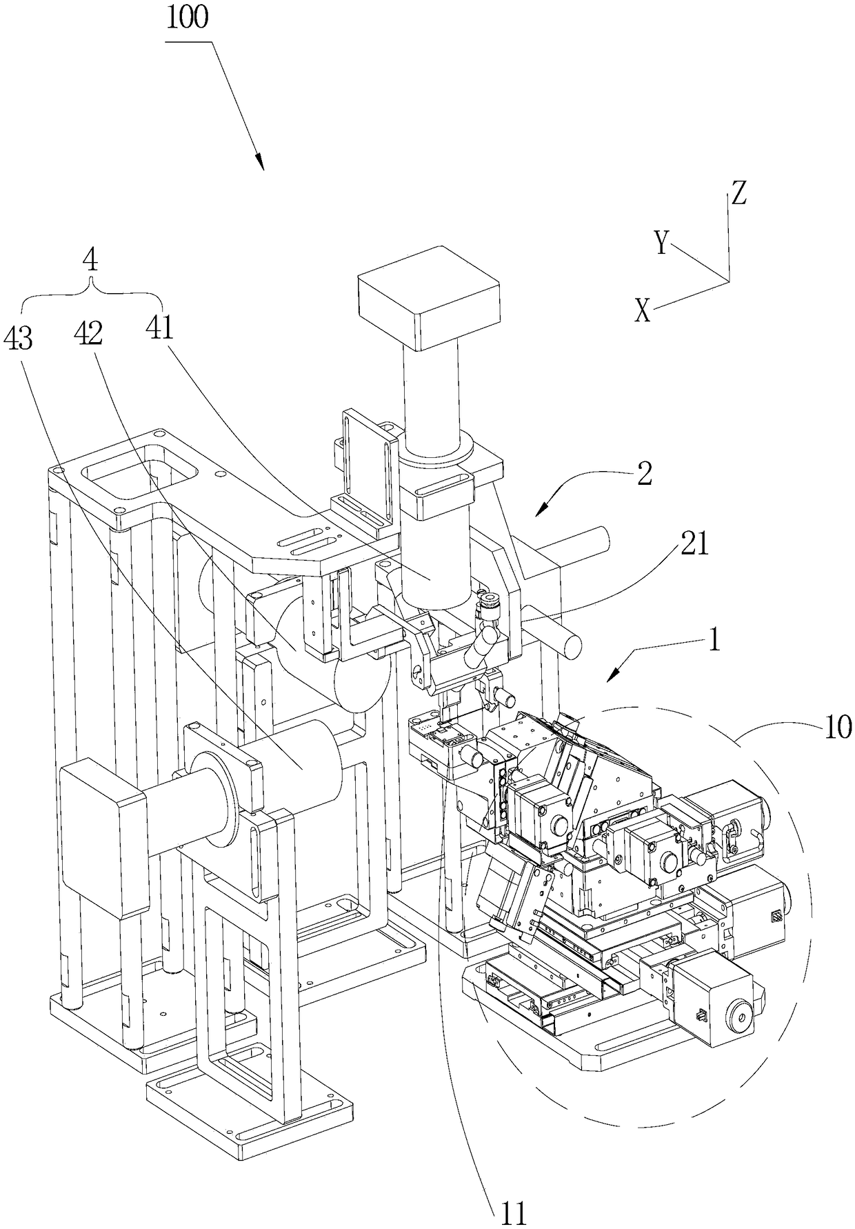
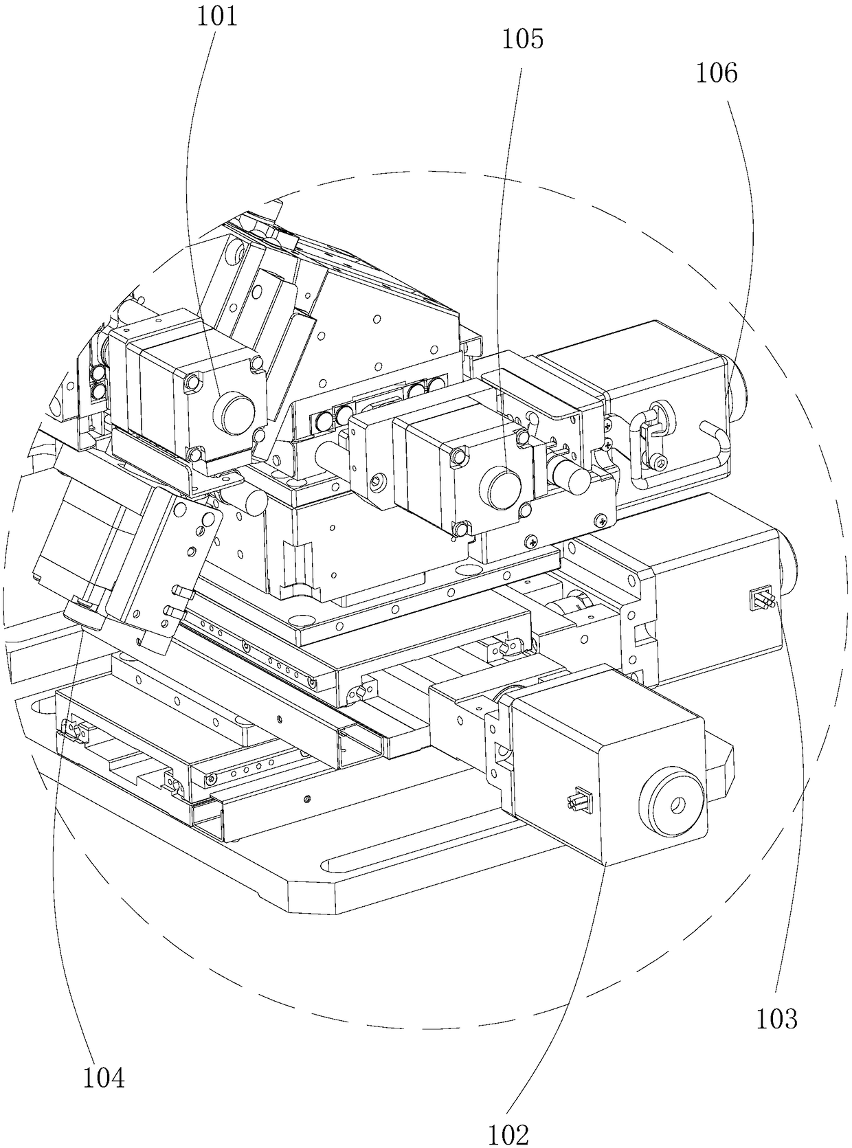
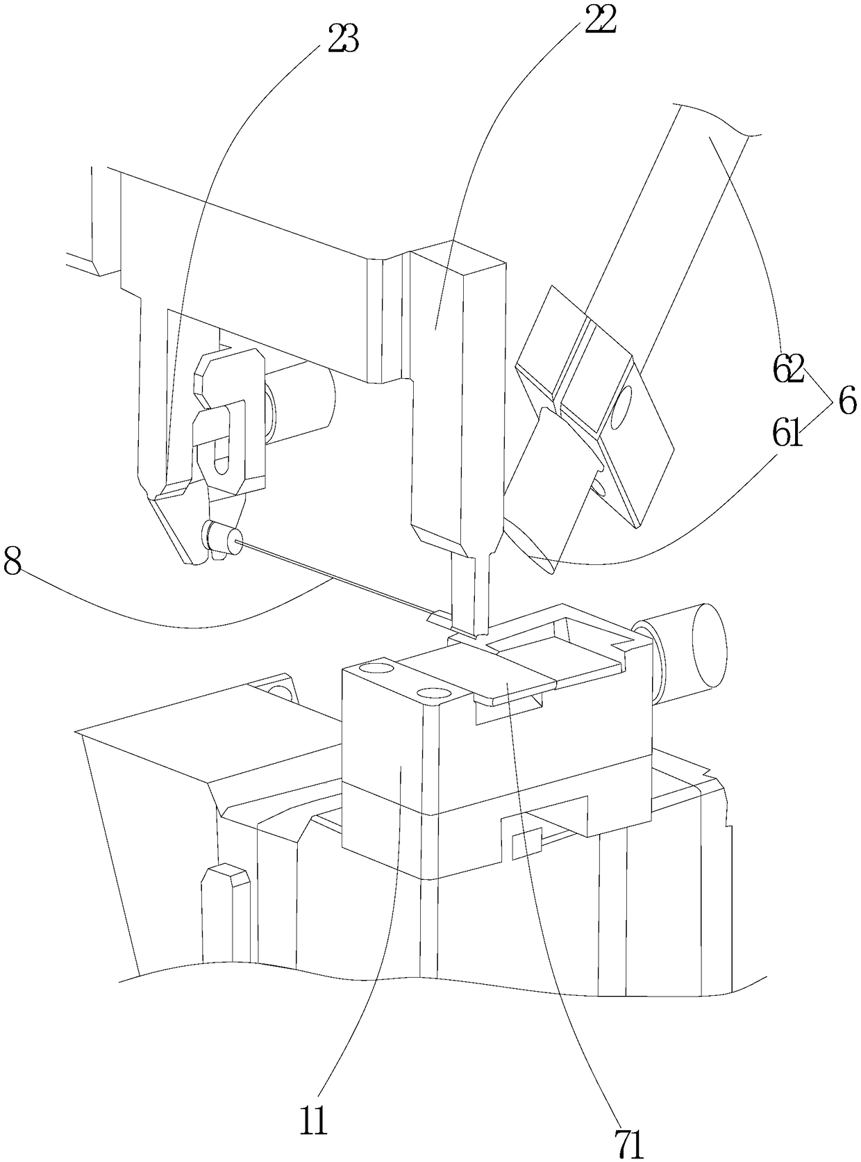
The present invention is suitable for the technical field of optical device package, and provides a coupled system of an optical device and a coupled method of an optical device. The system comprisesa six-axis coupled device, a three-dimensional mobile device, a current detection device and a camera monitoring device. The six-axis coupled device is configured to drive a PD array to move and perform coupling of an arrayed waveguide grating, and the camera monitoring device is configured to perform monitoring of a relative position and a relative distance between the PD array and the arrayed waveguide grating in the coupled process. The coupled system of the optical device and the coupled method of the optical device are provided with the camera monitoring device to perform shooting and monitoring of the relative position and the relative distance between the PD array and the arrayed waveguide grating to avoid the problem that the PD array and the arrayed waveguide grating are collideddue to manual determination faults when a distance between the PD array and the arrayed waveguide grating is too small and prevent the PD array and the arrayed waveguide grating from being extruded and damaged compared to a mode of eye observation of operators so as to improve the coupled efficiency between the PD array and the arrayed waveguide grating on this basis and improve the package yield.

Description

technical field [0001] The invention belongs to the technical field of packaging of optical devices, and in particular relates to a coupling system of an optical device and a coupling method of an optical device. Background technique [0002] At present, with the rapid development of optical technology, high-speed optical communication technology is applied in more and more fields. Large-capacity optical fiber communication system has great development potential and research value. Coarse Wavelength Division Multiplexing (CWDM) technology can tap the transmission potential of optical fiber better and has gradually attracted attention. [0003] Arrayed Waveguide Grating (AWG) is a device fabricated on a chip substrate using PLC (planar optical waveguide) technology, consisting of an input waveguide, an input planar waveguide, an array waveguide, an output planar waveguide, and an output waveguide. When an optical signal with multiple wavelengths enters the input planar wave...

Claims


Application Information

Patent Timeline
Patent Type & Authority Applications(China)
IPC IPC(8): G02B6/42G02B6/43
CPCG02B6/4221G02B6/43
Inventor 黄劲威孙辉季红岩庄礼杰
Owner APAT OPTOELECTRONICS COMPONENTS
Learn More