Supercharge Your Innovation With Domain-Expert AI Agents!

Adjustable cable bridge and preparation method thereof

A cable tray and adjustable technology, applied in the field of adjustable cable tray and its preparation, can solve the problems of small use range of cables and inability to adjust the cable tray, and achieve the effects of light weight, improved strength and good castability

Inactive Publication Date: 2018-11-23
ZHENJIANG YIBAO ELECTRICAL TECH CO LTD
View PDF7 Cites 1 Cited by
  • Summary
  • Abstract
  • Description
  • Claims
  • Application Information

AI Technical Summary

Problems solved by technology

[0003] The existing cable trays are all located in the same plane, and the range of use when erecting cables is small, and the cable trays cannot be adjusted according to actual needs

Method used


Image

  • Adjustable cable bridge and preparation method thereof

Examples


Embodiment 1

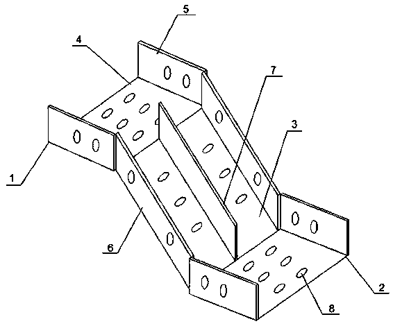
[0033] This embodiment provides an adjustable cable bridge, including a first bridge 1, a second bridge 2 and a connecting plate 3 connecting the first bridge 1 and the second bridge 2, the first bridge 1 and the second bridge 2 are parallel to each other and On the same straight line, the first bridge frame 1 and the second bridge frame 2 both include a bottom plate 4 and a side plate 5, the left end of the connecting plate 3 is hinged with the right end of the bottom plate 4 of the first bridge frame 1, and the right end of the connecting plate 3 is connected with the second bridge frame The left end of the base plate 4 of 2 is hinged. Both sides of the connecting plate 3 are provided with side plates 6 perpendicular to the connecting plate 3 , and the two side plates 6 are located between the two side plates 5 . The bottom plate 4 , the side plate 5 , the connecting plate 3 and the side plate 6 are all provided with cooling holes 8 .

[0034] A partition plate 7 along the ...

Embodiment 2

[0044] This embodiment provides an adjustable cable bridge, including a first bridge 1, a second bridge 2 and a connecting plate 3 connecting the first bridge 1 and the second bridge 2, the first bridge 1 and the second bridge 2 are parallel to each other and On the same straight line, the first bridge frame 1 and the second bridge frame 2 both include a bottom plate 4 and a side plate 5, the left end of the connecting plate 3 is hinged with the right end of the bottom plate 4 of the first bridge frame 1, and the right end of the connecting plate 3 is connected with the second bridge frame The left end of the base plate 4 of 2 is hinged. Both sides of the connecting plate 3 are provided with side plates 6 perpendicular to the connecting plate 3 , and the two side plates 6 are located between the two side plates 5 . The bottom plate 4 , the side plate 5 , the connecting plate 3 and the side plate 6 are all provided with cooling holes 8 .

[0045] A partition plate 7 along the ...

Embodiment 3

[0055] This embodiment provides an adjustable cable bridge, including a first bridge 1, a second bridge 2 and a connecting plate 3 connecting the first bridge 1 and the second bridge 2, the first bridge 1 and the second bridge 2 are parallel to each other and On the same straight line, the first bridge frame 1 and the second bridge frame 2 both include a bottom plate 4 and a side plate 5, the left end of the connecting plate 3 is hinged with the right end of the bottom plate 4 of the first bridge frame 1, and the right end of the connecting plate 3 is connected with the second bridge frame The left end of the base plate 4 of 2 is hinged. Both sides of the connecting plate 3 are provided with side plates 6 perpendicular to the connecting plate 3 , and the two side plates 6 are located between the two side plates 5 . The bottom plate 4 , the side plate 5 , the connecting plate 3 and the side plate 6 are all provided with cooling holes 8 .

[0056] A partition plate 7 along the ...


PUM


Abstract

The invention discloses an adjustable cable bridge, and relates to the technical field of cable bridges. The adjustable cable bridge comprises a first bridge frame, a second bridge frame. and a connecting plate which is connected with the first bridge frame and the second bridge frame; the first bridge frame and the second bridge frame are parallel to each other and are located on the same straight line; each of the first bridge frame and the second bridge frame comprises a bottom plate and side plates separately; and one end of the connecting plate is hinged to the end part of the bottom plate of the first bridge frame, and the other end of the connecting plate is hinged to the end part of the bottom plate of the second bridge frame. The invention further discloses a preparation method ofthe adjustable cable bridge. According to the adjustable cable bridge, the first bridge frame and the second bridge frame can be adjusted into horizontal planes with different heights, so that an erected cable can be bent in a vertical plane, thereby adjusting the height of the cable.

Description

technical field [0001] The invention relates to the technical field of cable trays, in particular to an adjustable cable tray and a preparation method thereof. Background technique [0002] Cable tray is a cable laying device that can standardize, systematize, and generalize the laying of wires, cables, and pipe cables. Its basic types include the following: trough cable tray, a fully enclosed cable tray, which is most suitable for Laying of computer cables, communication cables, thermocouple cables and other highly sensitive system control cables has good shielding interference and cable protection in heavy corrosion environments; the tray type cable tray has light weight, large load, and shape It has the advantages of beautiful appearance, simple structure, and convenient installation. It is suitable for the installation of power cables and the laying of control cables; the stepped cable tray is suitable for laying cables with large diameters, especially for high and low p...

Claims


Application Information

Patent Timeline
IPC IPC(8): H02G3/04C25D11/06C22F1/047C22C21/08C22C1/02
CPCH02G3/0437C22C1/026C22C21/08C22F1/047C25D11/06
Inventor 姚军
Owner ZHENJIANG YIBAO ELECTRICAL TECH CO LTD
Features
  • R&D
  • Intellectual Property
  • Life Sciences
  • Materials
  • Tech Scout
  • Unparalleled Data Quality
  • Higher Quality Content
  • 60% Fewer Hallucinations
Learn More