Cogging torque separation method of permanent magnet synchronous motor under load condition

A cogging torque and load-carrying technology, which is applied in the field of electrical engineering, can solve problems such as the complexity of cogging torque calculation, and achieve good economic benefits.

Inactive Publication Date: 2018-11-23
NANJING NORMAL UNIVERSITY
View PDF3 Cites 2 Cited by
  • Summary
  • Abstract
  • Description
  • Claims
  • Application Information

AI Technical Summary

Problems solved by technology

[0003] The technical problem to be solved by the present invention: Aiming at the complexity of cogging torque calculation under load, a cogging torque separation method for permanent magnet synchronous motor under load is proposed

Method used


Image

  • Cogging torque separation method of permanent magnet synchronous motor under load condition
  • Cogging torque separation method of permanent magnet synchronous motor under load condition
  • Cogging torque separation method of permanent magnet synchronous motor under load condition

Examples


Embodiment

[0050] The implementation steps of this embodiment are as follows:

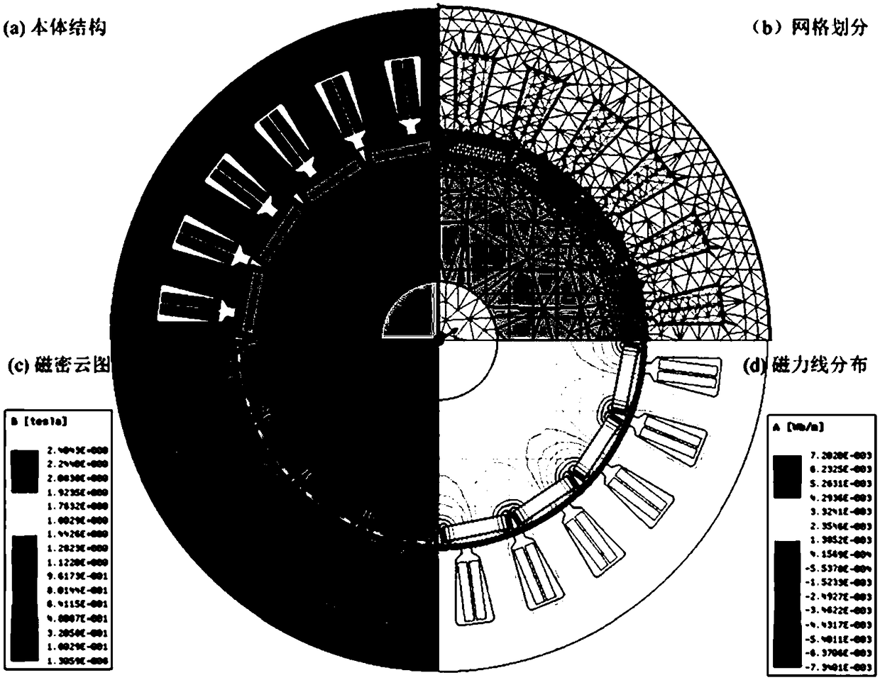
[0051] (1) This example uses a two-dimensional model of a 24-slot, 16-pole "one" type embedded permanent magnet synchronous motor. In the finite element analysis software Ansoft, set various parameters according to the following table, and get the following figure 1 The 2D static model shown.

[0052]

[0053] (2) According to the three-phase current of the motor under the condition of load operation, the stator winding current i which is the same as the actual situation is set by the finite element analysis software a =15cos(400πt), The unit is A.

[0054] (3) According to the rotating speed of the motor under load operation, then set the same motor running speed n=1500 as the actual situation through the finite element analysis software, and the unit is r / min;

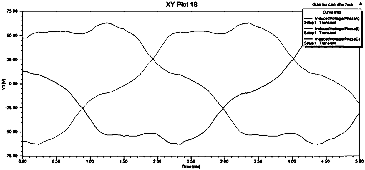
[0055] (4) In the solver of the finite element analysis software, the back electromotive force e of the three-phase winding is obtained a 、...


PUM


Abstract

The invention discloses a cogging torque separation method of a permanent magnet synchronous motor under a load condition. The cogging torque separation method comprises the steps of step 1, establishing a motor model in finite element analysis software, such as Ansoft, COMSOL and the like; step 2, injecting three-phase symmetric currents: injecting three-phase symmetric currents of ia, ib and icinto a stator winding of the motor model according to the running state of the motor under the load condition; step 3, according to the running speed of the motor under the actual condition, synchronizing the running speed n of the motor; step 4, obtaining counter electromotive force; step 5, calculating the output power of an armature current: according to the three-phase currents and the counterelectromotive force obtained in the step 2 and the step 4, solving the output power P of the armature current; step 6, calculating the output torque of the armature current: according to the operation rotating speed n and the armature current output power P obtained in the step 3 and the step 5, solving the output torque Tarm of the armature current; and step 7, carrying out cogging torque separation.

Description

technical field [0001] The invention belongs to the technical field of electrical engineering, and in particular relates to a cogging torque separation method of a permanent magnet synchronous motor under load conditions. Background technique [0002] Permanent magnet synchronous motors have the advantages of high efficiency, small size, and good control performance, and are widely used in daily necessities, industrial production, and other fields. Although permanent magnet synchronous motor has many advantages, it still has some problems, cogging torque is one of them. The cogging torque will cause problems such as motor speed fluctuation and noise, and affect the performance of the motor. Therefore, the research on the generation mechanism and optimization analysis of the permanent magnet synchronous motor cogging torque is very important. Under no-load conditions, since the air gap flux density of the stator slot is only affected by the permanent magnet, the analysis of ...

Claims


Application Information

Patent Timeline
Patent Type & Authority Applications(China)
IPC IPC(8): H02P21/20
CPCH02P21/20
Inventor 王伟业邱鑫马辉杨建飞冯春梅施建平杨继全朱兵董艮滔李思祥
Owner NANJING NORMAL UNIVERSITY
Why Eureka
Try Eureka