
A topology-based virtual switching model with pluggable flow management protocols

A technology for managing protocols and topology structures, applied in data exchange networks, digital transmission systems, electrical components, etc., can solve problems such as impossible implementation and complex switch configuration tasks

Active Publication Date: 2018-11-23
HONOR DEVICE CO LTD
View PDF6 Cites 2 Cited by
  • Summary
  • Abstract
  • Description
  • Claims
  • Application Information

AI Technical Summary

Problems solved by technology

In many cases, different virtual switch implementations with different protocols from different vendors can be applied to a single system, making the task of switch configuration complex or even impossible

Method used


Image

  • A topology-based virtual switching model with pluggable flow management protocols
  • A topology-based virtual switching model with pluggable flow management protocols
  • A topology-based virtual switching model with pluggable flow management protocols

Examples


Embodiment Construction

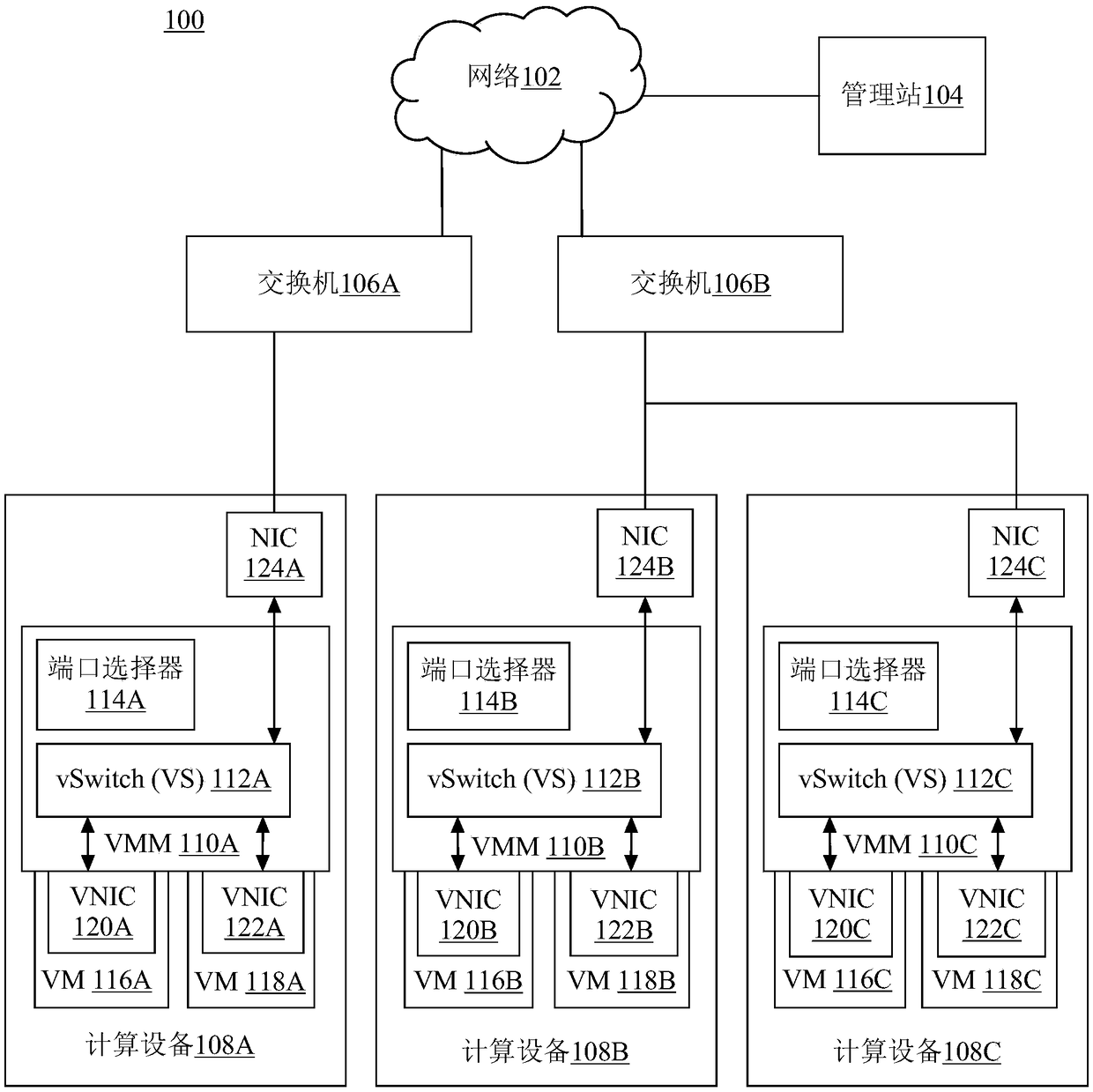
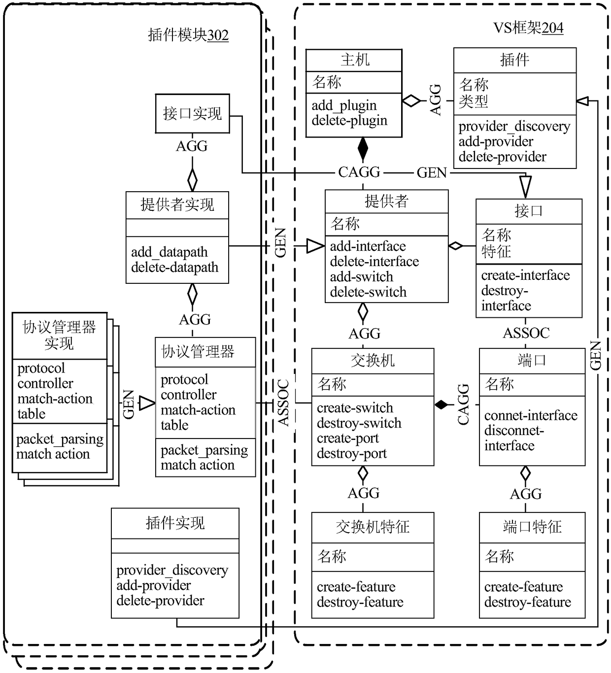
[0039] The present invention relates to a technique for a virtual switch framework using a unified topology management interface and supporting multiple data plane providers with different flow management protocols enabled by dynamically pluggable modules.

[0040] Multiple flow management protocols are supported in the virtual network switch, and the flow management protocol can be changed to another protocol at runtime without changing the topology configuration of the switch. The data plane provider is detected by a pluggable software module (or plug-in or plug-in module) that utilizes a network interface to identify and control the data-plane provider and enables the flow management protocol. Then, a switch topology is built by creating a virtual switch object and adding ports to the virtual switch object. Then, a data path is created on the data plane provider using the switch topology and the first flow management protocol. The network interfaces are respectively connec...


PUM


Abstract

The disclosure relates to technology for supporting multiple flow management protocols in a virtual network switch and changing a flow management protocol without changing switch topology configurations at run time. A data plane provider is detected via a pluggable software module (or plugin or plugin module) that identifies and controls the data plane provider with network interfaces and enablesflow management protocols. A switch topology is then constructed by creating a virtual switch object, adding ports to the virtual switch object. A datapath is then created using the switch topology and the first flow management protocol on the data plane provider. Network interfaces are connect to each ports respectively to enable communication among the entities attached to each network interfaceaccording to the first flow management protocol. The datapath can be later changed to use the second flow management protocol and retain the same topology at run time.

Description

[0001] This application claims a prior application to U.S. Nonprovisional Patent Application No. 15 / 077,461, filed March 22, 2016, entitled "A Topology-Based Virtual Switching Model With Pluggable Flow Management Protocol" Priority, the content of this earlier application is incorporated herein by reference. Background technique [0002] A network switch is a hardware device used to make data connections between devices. A switch can be used to receive, process and forward data packets to their intended destination according to a specific flow management protocol (or known as a data forwarding protocol). Furthermore, a network switch can have two planes: a control plane and a data plane. The control plane is the part of the system responsible for providing the stream management protocol functions and features of the system. The data plane is responsible for actually receiving data from the port connecting the switch with the external source, processing the data, and sending ...

Claims


Application Information

Patent Timeline
Patent Type & Authority Applications(China)
IPC IPC(8): H04L12/70H04L47/41
CPCH04L41/0816H04L41/0895H04L41/40H04L41/122H04L41/12H04L47/41H04L49/354
Inventor 逯云松陈炎
Owner HONOR DEVICE CO LTD
Learn More