Device for demonstration and testing of maglev train model

A technology of maglev train and model, applied in the field of electric traction drive, can solve the problem that the system cannot be unified

Active Publication Date: 2022-04-01
BEIJING JIAOTONG UNIV
View PDF7 Cites 0 Cited by
  • Summary
  • Abstract
  • Description
  • Claims
  • Application Information

AI Technical Summary

Problems solved by technology

[0003] At present, the display and testing of the maglev train model is generally divided into two systems, and the train model during the display process and the system during the experimental test cannot be unified

Method used


Image

  • Device for demonstration and testing of maglev train model
  • Device for demonstration and testing of maglev train model
  • Device for demonstration and testing of maglev train model

Examples


Embodiment

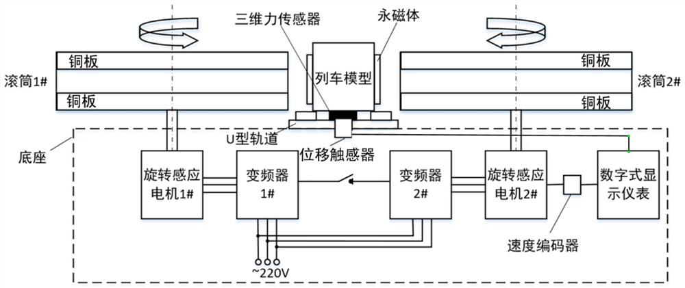
[0037] figure 1 It is a schematic diagram of the device structure for a maglev train model test of the present embodiment, referring to figure 1 , Permanent magnets are installed on both sides of the maglev train model, and the device includes: U-shaped track, two rollers and a base.

[0038] Two rotating induction motors (1# and 2#), two frequency converters (1# and 2#), speed encoders and digital display instruments are respectively installed on the base; two rollers (1# and 2#) The shaft center is perpendicular to the base, and is respectively connected with two rotating motors through rotating shafts. The two rotating motors turn in the opposite direction, and the working state of the rotating induction motor is controlled by the frequency converter to make it work in an electric state, which drives the drum to rotate, and produces relative motion with the permanent magnets on both sides of the car model to make the train model levitate.

[0039] The two frequency conver...


PUM


Abstract

The invention provides a device for demonstrating and testing a maglev train model, comprising: a U-shaped track, two rollers and a base; two rotating motors, two frequency converters, a speed encoder and a display are respectively installed on the base; The axes of the two rollers are perpendicular to the base, and are respectively connected to the two rotating motors through the rotating shaft; the U-shaped track is fixed on the base, and displacement sensors and three-dimensional force sensors are installed on the base between the U-shaped tracks. The type track is centrally symmetrical; the upper and lower sides of the outer surfaces of the two rollers are respectively equipped with annular copper plates; each rotating motor circuit is connected to a frequency converter, and then connected to the speed encoder and display, and the displacement sensor and the three-dimensional force sensor are connected through the circuit to the display. The device can directly and accurately detect the three-dimensional force, running speed and levitation height of the maglev model, so as to judge whether the maglev train model meets the design standard.

Description

technical field [0001] The invention relates to the technical field of electric traction transmission, in particular to a device for demonstrating and testing a maglev train model. Background technique [0002] Maglev train is an emerging modern means of transportation. It not only has the advantages of low noise, strong climbing ability, safety and environmental protection, low maintenance cost and small radius curve passing ability, but also an electromagnetic levitation train without wheel-rail contact. Not limited by adhesion. The engineering demonstration of the maglev train needs to be demonstrated through the experimental model, and various working conditions in the experimental research and development stage also need to be verified and analyzed through the experimental model; the levitation height of the maglev train will change during operation, so in the test stage It is necessary to obtain various performance indicators of the motor under different levitation he...

Claims


Application Information

Patent Timeline
Patent Type & Authority Patents(China)
IPC IPC(8): G09B25/00G01M17/08
CPCG09B25/00G01M17/08
Inventor 吕刚张贤周桐
Owner BEIJING JIAOTONG UNIV
Why Eureka
Try Eureka