New material stirring mixing device capable of changing stirring scope

A technology for mixing and mixing new materials, which is applied to mixers, mixers, mixer accessories and other directions with rotating mixing devices, which can solve the problems of large material volume, easy sedimentation and adsorption, and insufficient raw materials, so as to optimize the mixing effect, Avoid deposition adsorption, easy to use effect

Inactive Publication Date: 2018-11-27
佛山博发智能科技有限公司
View PDF10 Cites 9 Cited by
  • Summary
  • Abstract
  • Description
  • Claims
  • Application Information

AI Technical Summary

Problems solved by technology

The research of new materials is the advance of human beings to understand and apply material properties to a deeper level. In actual production applications, it is necessary to use a mixing device to mix the raw materials of new materials. Only stirring the materials often

Method used


Image

  • New material stirring mixing device capable of changing stirring scope
  • New material stirring mixing device capable of changing stirring scope
  • New material stirring mixing device capable of changing stirring scope

Examples


Embodiment 1

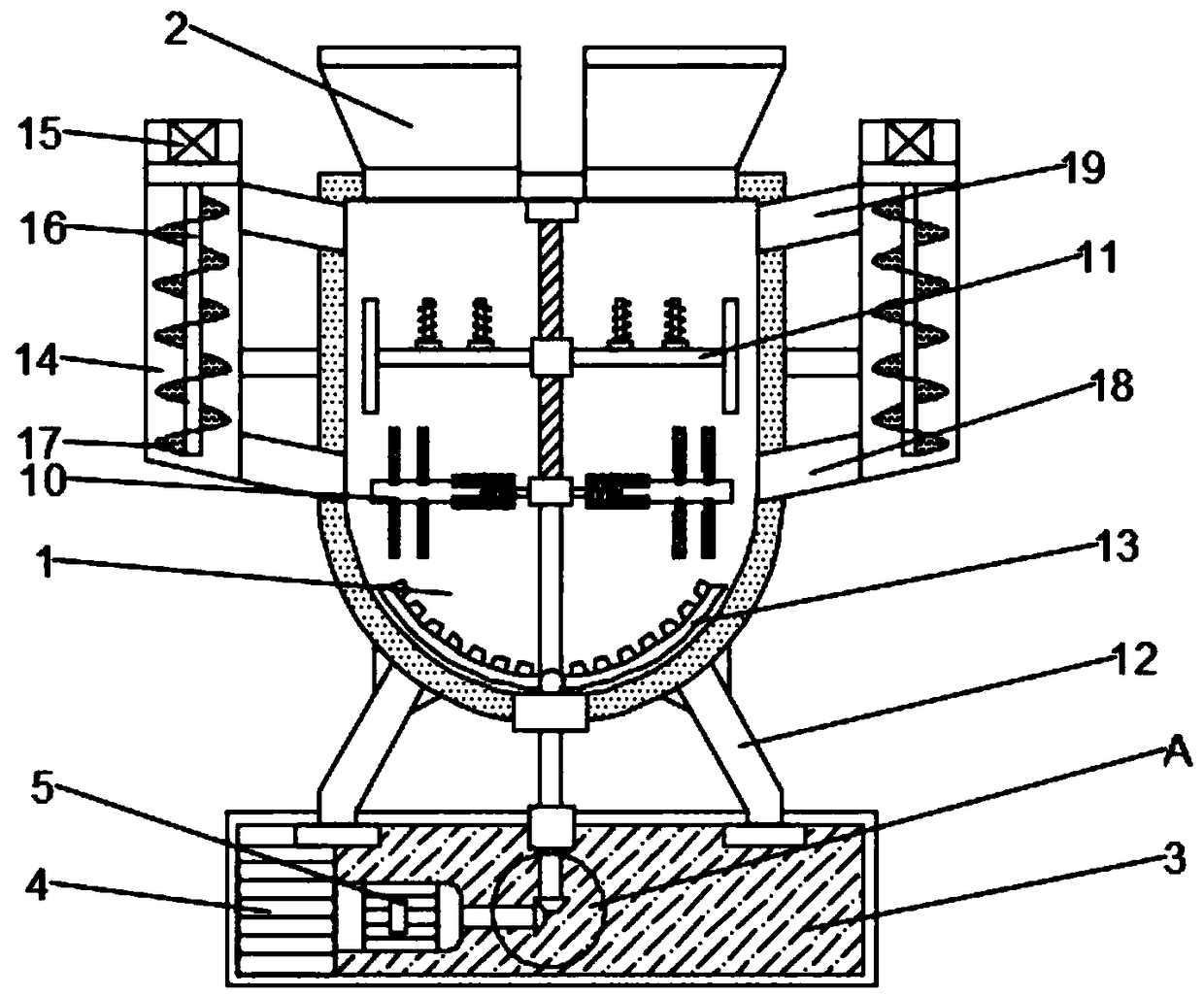
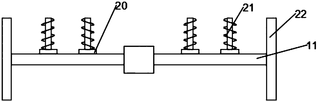
[0024] Such as Figure 1~5As shown, in the embodiment of the present invention, a new material raw material stirring and mixing device that can change the stirring range includes a housing 1, a material inlet 2, a supporting base 3, a first stirring shaft 10, a second stirring shaft 11, a support Legs 12 and a material circulation chamber 14, the bottom of the housing 1 is provided with a support base 3, the support legs 12 are welded symmetrically on both sides of the lower surface of the housing 1, the support legs 12 are arranged obliquely, and the lower ends of the support legs 12 are fixed On the upper surface of the support base 3, the inner cavity of the housing 1 is provided with a bottom stirring paddle 13, a first stirring shaft 10 and a second stirring shaft 11 in sequence from bottom to top, and two symmetrically arranged on the upper surface of the housing 1. Material inlet 2, two material circulation chambers 14 are vertically arranged symmetrically on both sides...

Embodiment 2

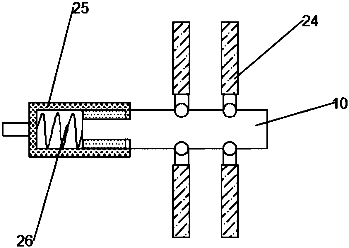
[0026] Such as figure 1 As shown, in this embodiment, the connection mode between the mixing plate 24 and the first stirring shaft 10 is hinged, so that the first stirring shaft 10 can slide horizontally along the cavity of the limiting chute 25 while achieving The limiting chute 25 swings around the first stirring shaft 10, thereby strengthening the stirring and mixing effect, avoiding the occurrence of dynamic balance during the mixing and stirring process, thereby affecting the normal mixing of raw materials; Parts match.

[0027] The working principle of the present invention is: the raw material flows into the inner cavity of the housing 1 through the material inlet 2, the servo motor 5 is started, and the servo motor 5 starts to drive the first rotating shaft 6 and the second rotating shaft 9 Rotate with the limiting chute 25, and then drive the first stirring shaft 10 to rotate, and at the same time drive the first stirring shaft 10 to slide along the inner cavity of t...


PUM


Abstract

The invention discloses a new material stirring mixing device capable of changing a stirring scope. The new material stirring mixing device comprises a shell, feeding ports, a support base, a first stirring shaft, a second stirring shaft and material circulating chambers; the support base is arranged at the bottom of the shell; support legs are symmetrically welded on the two sides of the lower surface of the shell; the support legs are bias arranged; the lower ends of the support legs are fixed on the upper surface of the support base; a bottom stirring paddle, the first stirring shaft and the second stirring shaft are successively arranged in an inner chamber of the shell from bottom to top; two feeding ports are symmetrically formed in the upper surface of the shell; two material circulating chambers are symmetrically vertical arranged on two side walls of the shell; the new material stirring mixing device is characterized in that a storage battery is welded on a left side wall of the inner chamber of the support base; a servo motor is arranged on the right side of the storage battery. The new material stirring mixing device is convenient in use, is capable of continuously changing the stirring scope so as to optimize the mixing stirring effect of raw materials and is capable of realizing efficient mixing of the raw materials.

Description

technical field [0001] The invention relates to the technical field of new material production equipment, in particular to a new material raw material stirring and mixing device capable of changing the stirring range. Background technique [0002] New materials refer to some materials that are newly developed or under research and development, and have superior performance, which have better performance than traditional materials. New material technology is a technology that creates new materials that can meet various needs through a series of research processes such as physical research, material design, material processing, and test evaluation according to human will. The output value of the world's material industry is growing at a rate of about 30% per year. New chemical materials, microelectronics, optoelectronics, and new energy have become the most active, fastest-growing, and most promising fields of new materials for investors. Material innovation has become a drivi...

Claims


Application Information

Patent Timeline
IPC IPC(8): B01F15/00B01F13/10B01F7/00
CPCB01F27/092B01F27/118B01F27/2323B01F33/85B01F35/32025B01F35/4121
Inventor 王利
Owner 佛山博发智能科技有限公司
Why Eureka
Try Eureka