
Laser cutting machine tool for machining plates

A technology of laser cutting and plate processing, which is applied in laser welding equipment, metal processing equipment, manufacturing tools, etc., can solve the problems of low automation of machine tools and inconvenient use of machine tools, so as to reduce manual operation steps, improve automation, and facilitate The effect of using

Inactive Publication Date: 2018-11-27
SUZHOU DANENG LASER TECH CO LTD
View PDF0 Cites 1 Cited by
  • Summary
  • Abstract
  • Description
  • Claims
  • Application Information

AI Technical Summary

Problems solved by technology

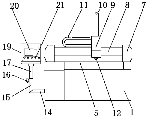
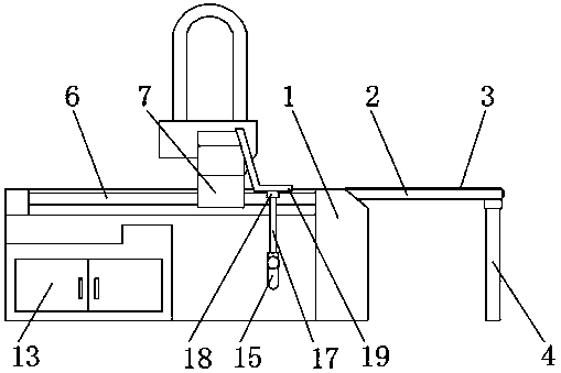
[0002] The laser cutting machine tool for plate processing uses high-power-density laser beams to irradiate the plate to be cut, so that the plate is quickly heated to the vaporization temperature, and evaporates to form holes. As the beam moves to the plate, the holes continuously form narrow slits. The cutting of the plate is completed, but the existing laser cutting machine tools for plate processing have certain defects in use. Improvements to Laser Cutting Machine Tools for Sheet Metal Processing

Method used


Image

  • Laser cutting machine tool for machining plates
  • Laser cutting machine tool for machining plates

Examples


Embodiment Construction

[0018] The following will clearly and completely describe the technical solutions in the embodiments of the present invention with reference to the accompanying drawings in the embodiments of the present invention. Obviously, the described embodiments are only some, not all, embodiments of the present invention.

[0019] refer to Figure 1-2 , a laser cutting machine tool for plate processing, comprising a base 1, a bracket 2 is fixedly installed on the outer surface of the front end of the base 1, a conveyor belt 3 is arranged on the outer surface of the upper end of the bracket 2, and a support foot 4 is fixedly installed on the outer surface of the lower end of the bracket 2 , both sides of the outer surface of the base 1 are fixedly equipped with guide rods 6, the upper end of the base 1 is located at the position of the outer surface of the guide rod 6 to be provided with a connecting seat 7, the number of the connecting seats 7 is two groups, the two groups of connecting ...


PUM


Abstract

The invention discloses a laser cutting machine tool for machining plates. The laser cutting machine tool comprises a base, a support is fixedly mounted on the outer surface of the front end of the base, a conveying belt is arranged on the outer surface of the upper end of the support, supporting legs are fixedly mounted on the outer surface of the lower end of the support, guide rods are fixedlymounted on the outer surfaces of two sides of the base, two groups of connecting seats are arranged at the upper end of the base and positioned on the outer surfaces of the guide rods, a beam is fixedly mounted between two groups of connecting seats, a sliding seat is movably mounted on the outer surface of the upper end of the beam, a lifting track is arranged on the outer surface of the upper end of the sliding seat, a horizontal movable track is arranged on the outer surface of one side of the sliding seat and positioned above the beam, and a fixed rod is fixedly mounted on the outer surface of the base and positioned in the front of a maintenance door. According to the laser cutting machine tool, manual operation steps can be decreased, automation degree is improved, and the machine tool can be conveniently used and has practicability.

Description

technical field [0001] The invention relates to the technical field of laser cutting, in particular to a laser cutting machine tool for plate processing. Background technique [0002] The laser cutting machine tool for plate processing uses high-power-density laser beams to irradiate the cut plate, so that the plate is quickly heated to the vaporization temperature, and evaporates to form holes. As the beam moves to the plate, the holes continuously form narrow slits. The cutting of the plate is completed, but the existing laser cutting machine tools for plate processing have certain defects in use. Improvements are made to laser cutting machine tools for sheet metal processing. Contents of the invention [0003] The purpose of the present invention is to solve the shortcomings in the prior art, and propose a laser cutting machine tool for plate processing. [0004] In order to achieve the above object, the present invention adopts the following technical solutions: [...

Claims


Application Information

Patent Timeline
IPC IPC(8): B23K26/38B23K26/70
CPCB23K26/38B23K26/702
Inventor 孙正元
Owner SUZHOU DANENG LASER TECH CO LTD
Learn More