


Quick Research
Generate reliable direction feasibility study reports for your R&D in just a few steps.

Technical Q&A
Discover and master advanced knowledge NOW. Basics, ideas, possibilities, all at once.

Find Solutions
As an expert in R&D theories, this can generate solutions to your technical problems instantly.

Evaluate Feasibility
Analyze your overall solution with one click, know your potential R&D risks in advance.

Monitor Landscape
Get weekly tech updates, stay abreast of the latest tech innovations and key insights.
Support body for erecting precast plate and construction method thereof
A technology of prefabricated panels and supports, which is applied in the processing of building materials, construction, and building construction. It can solve problems such as the inability of liners to be reused, insufficient concrete strength, and concrete damage to achieve good economic benefits and save labor costs. , Improve the effect of construction speed
- Summary
- Abstract
- Description
- Claims
- Application Information
AI Technical Summary
Problems solved by technology
Method used
Image

Examples
Embodiment 1
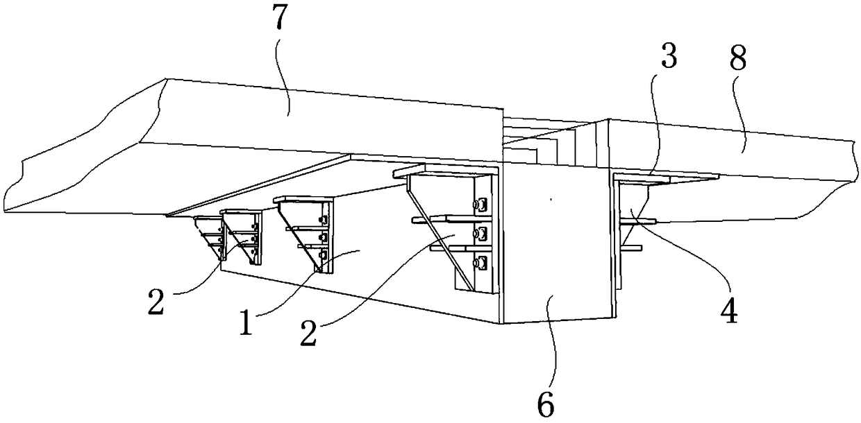
[0048] Such as figure 1 , figure 2 As shown, a support body for erecting a prefabricated slab includes a first formwork 1 and a second formwork 3 respectively arranged on both sides of a prefabricated beam 6, and the first formwork 1 includes a first formwork fixing part 1-1 fixed together And the first template supporting part 1-2. The first formwork supporting part 1-2 and the second formwork supporting part 3-2 extend a distance from the two sides of the prefabricated beam 6 to both sides respectively, and the first formwork supporting part 1-2 and the second formwork supporting part 3-2 is flush with the top of the prefabricated beam 6, and the first formwork support part 1-2 and the second formwork support part 3-2 are used to support the prefabricated slab. The prefabricated slab does not generate pressure on the prefabricated beam 6, the prefabricated beam 6 is protected, and the prefabricated slab is firmly supported.
[0049]Several first corbels 2 are arranged be...
Embodiment 2
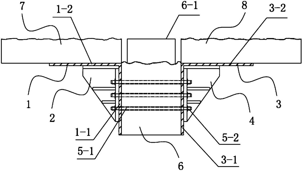
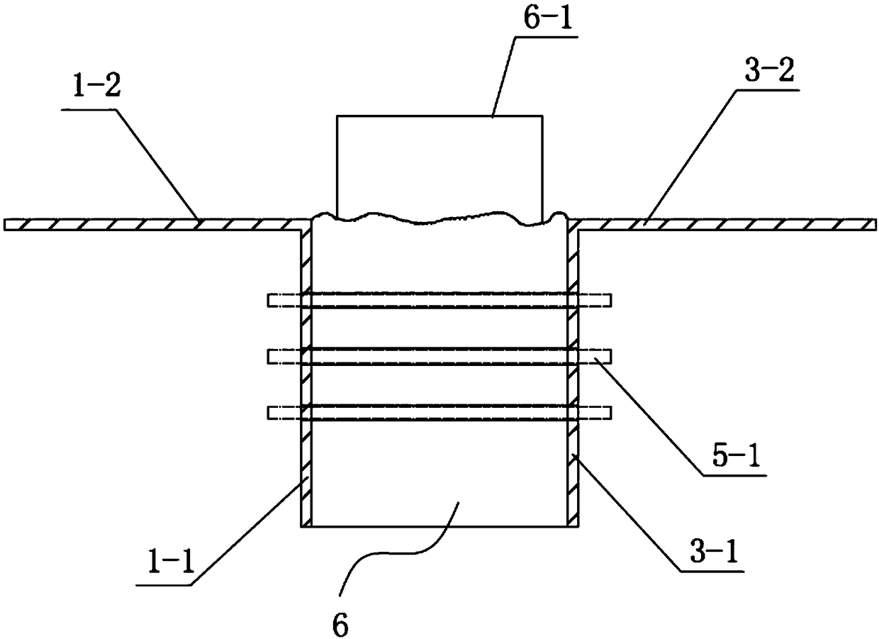
[0071] The main structure of this embodiment is the same as that of Embodiment 1, and the similarities will not be repeated here. The difference is that: image 3 As shown, the two sides of the prefabricated beam 6 are respectively provided with a first formwork 1 and a second formwork 3, using the bolt holes reserved when pouring the prefabricated beam 6, several bolts 5-1 pass through the prefabricated beam 6, and pass through several bolts 5-1. -1 and nuts 5-2 fix the first formwork 1 and the second formwork 3 to the prefabricated beam 6, the first prefabricated plate 7 and the second prefabricated plate 8 are placed on the first formwork 1 and the second formwork 3 respectively, and the second Pouring, the prefabricated beam 6 is combined with the first prefabricated slab 7 and the second prefabricated slab 8 as a whole. The first template 1 and the second template 3 are detachable and reused. The first formwork 1 and the second formwork 3 need to meet certain bending res...
Embodiment 3
[0073] The main structure of this embodiment is the same as that of Embodiment 1, and the similarities will not be repeated here. The difference is that: Figure 4 As shown, the two sides of the prefabricated beam 6 are respectively provided with the first corbel 2 and the second corbel 4, using the bolt holes reserved when pouring the prefabricated beam 6, several bolts 5-1 pass through the prefabricated beam 6, pass through several Bolts 5-1 and nuts 5-2 fix the first corbel 2 and the second corbel 4 to the prefabricated beam 6, and the first prefabricated plate 7 and the second prefabricated plate 8 rest on the first corbel 2 and the second corbel respectively. On the leg 4, the secondary pouring is performed to make the prefabricated beam 6, the first prefabricated slab 7 and the second prefabricated slab 8 be integrated into a whole. The first corbel 2 and the second corbel 4 are detachable and reused. The first corbel 2 and the second corbel 4 need to meet certain bendi...
PUM
 Abstract
Description
Claims
Application Information
 - R&D Engineer
- R&D Manager
- IP Professional
- Industry Leading Data Capabilities
- Powerful AI technology
- Patent DNA Extraction
Browse by: Latest US Patents, China's latest patents, Technical Efficacy Thesaurus, Application Domain, Technology Topic, Popular Technical Reports.
© 2024 PatSnap. All rights reserved.Legal|Privacy policy|Modern Slavery Act Transparency Statement|Sitemap|About US| Contact US: help@patsnap.com