A permanent magnet double disc brake and a braking method thereof

A brake and permanent magnet technology, applied in the direction of brake type, axial brake, brake actuator, etc., can solve the problems of magnetic flux leakage, permanent magnet retarder magnetic flux leakage, etc., to reduce wear, avoid magnetic leakage, prolong the The effect of service life

Active Publication Date: 2018-11-27
JIANGSU UNIV
View PDF10 Cites 5 Cited by
  • Summary
  • Abstract
  • Description
  • Claims
  • Application Information

AI Technical Summary

Problems solved by technology

However, most of the traditional permanent magnet retarders require a separate control mechanism. In the non-working state, there is a common problem of magnetic flux leakage.
[0005] Chinese patent (CN201310539585.X) discloses a double-disk permanent magnet retarder for vehicles, including a rotor assembly and a stator assembly, wherein the rotor assembly is composed of two rotor disks, and the stator assembly has two permanent magnets arranged at intervals. Composed of magnet brackets, the two magnet brackets are controlled by the operating mechanism to rotate at a certain angle to switch between the working state and the non-working state. It has certain innovations, but requires an additional operating mechanism. At the same time, this method has traditional permanent magnet retarders Flux leakage problem

Method used


Image

  • A permanent magnet double disc brake and a braking method thereof
  • A permanent magnet double disc brake and a braking method thereof
  • A permanent magnet double disc brake and a braking method thereof

Examples


Embodiment Construction

[0026] The following will be described in detail in conjunction with the accompanying drawings, but the protection scope of the present invention is not limited thereto.

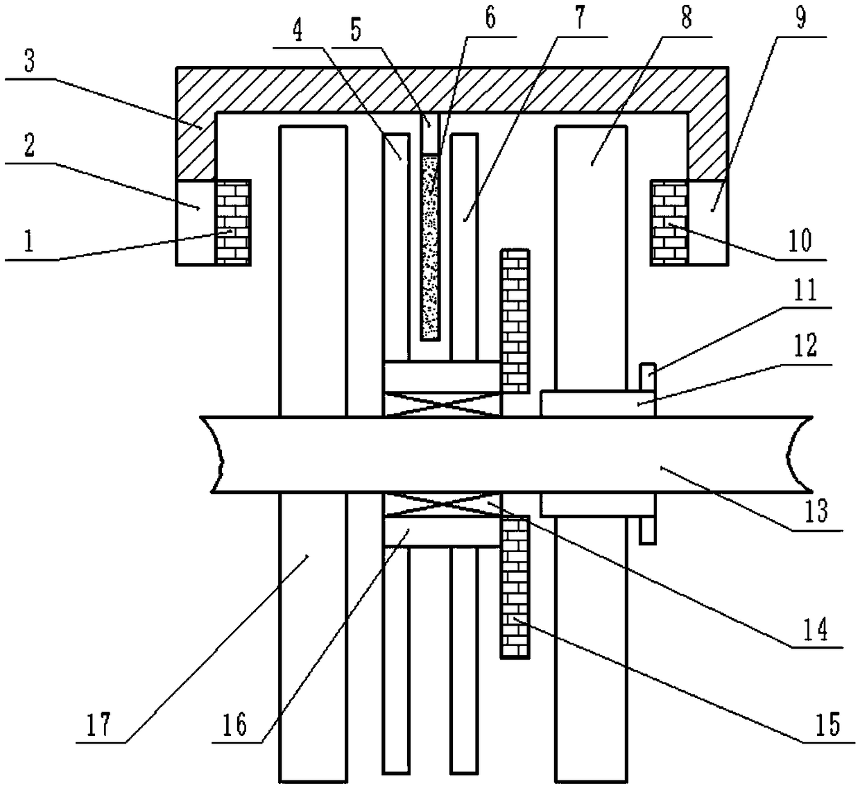
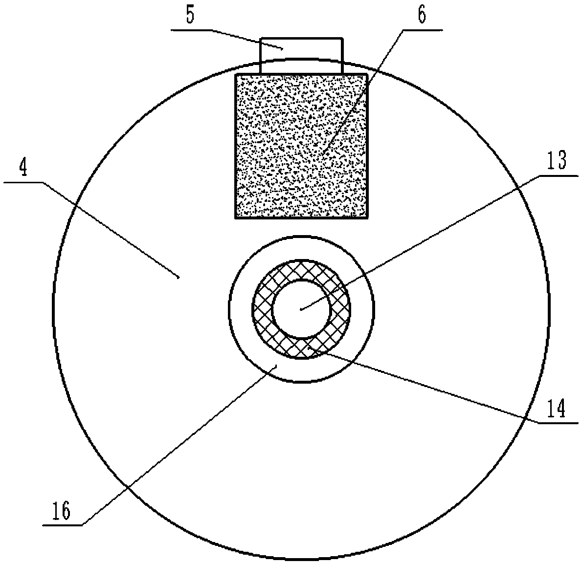
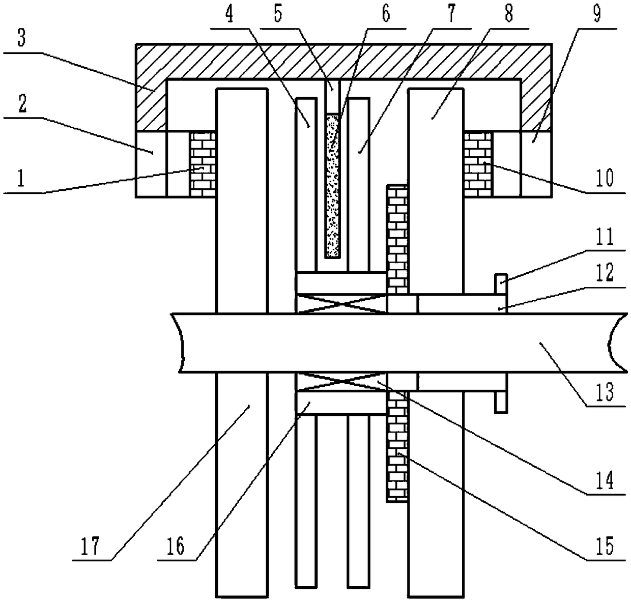
[0027] as attached figure 1 , 2 As shown, a kind of permanent magnet double disc brake of the present invention comprises inner brake disc 8, outer brake disc 17, connecting shaft 13, sliding gear 12, bearing 14, permanent magnet ring 11, double disc brake caliper 3, permanent magnet The connecting block 5 and the permanent magnet brake assembly; the outer brake disc 17, the bearing 14 and the sliding gear 12 are coaxially installed on the connecting shaft 13 in sequence from left to right, and the connecting shaft 13 is connected with the wheel hub and the axle shaft on the vehicle body; The moving disc 8 can be slidably installed on the sliding gear 12, and the connecting shaft 13, the outer brake disc 17, the bearing 14, the sliding gear 12, and the inner brake disc 8 are coaxial.

[0028] The permanent...


PUM


Abstract

The invention discloses a permanent magnet double disc brake and a braking method thereof, comprises an inner brake disc, an outer brake disc, a connecting shaft, a sliding gear, a bearing, a permanent magnet ring, a double-disc brake caliper, a permanent magnet connecting block and a permanent magnet brake assembly, wherein the permanent magnet brake assembly is arranged between the outer brake disc and the inner brake disc and comprises a permanent magnet, a first rotor disc, a second rotor disc, a rotor connecting sleeve and an intermediate friction plate. A permanent magnet double disc brake can provide two braking modes under the working state: a pure friction braking mode and a compound braking mode of friction braking and permanent magnet braking. Through the axial movement of the inner brake disc, the interruption and connection of the power transmission are realized, and the magnetic flux leakage phenomenon of the existing permanent magnet retarder on the market is avoided. The utility model has the advantages of no additional permanent magnet braking operation control mechanism, both permanent magnet auxiliary braking energy-saving, effective reduction of friction disc wear and large braking torque of the double-disc brake, and good heat dissipation performance.

Description

technical field [0001] The invention relates to an automobile brake, in particular to a permanent magnet double disc brake and a braking method thereof. Background technique [0002] The braking system of a car can be divided into four types according to its functions: service braking, second braking system, parking braking and auxiliary braking. There are mainly two types of service braking systems: disc brakes and drum brakes. Disc brakes have fast heat dissipation, light weight, simple structure, and easy adjustment. Especially when the load is high, it has good high temperature resistance and stable braking effect. Now most of the front wheel brakes of cars use disc brakes to ensure that the car has high directional stability during braking. Although disc brakes have many advantages, frequent or long-term frictional braking will generate a lot of heat, which will cause the friction plate to overheat. If the heat cannot be dissipated in time, the braking performance will...

Claims


Application Information

Patent Timeline
Patent Type & Authority Applications(China)
IPC IPC(8): F16D55/22F16D63/00F16D65/18F16D121/18F16D121/04F16D123/00
CPCF16D55/22F16D63/00F16D65/18F16D2121/04F16D2121/18F16D2123/00
Inventor 何仁张立伟
Owner JIANGSU UNIV
Why Eureka
Try Eureka