Dynamic Modeling Method for Spring-Varying Cross-Section Disk-Blade System

A dynamic modeling and blade system technology, applied in special data processing applications, instruments, electrical digital data processing, etc., can solve problems such as the inability to consider the disc as a variable-section disc, and the inconsistency with the actual application shape of the roulette.

Active Publication Date: 2018-11-27
NORTHEASTERN UNIV
View PDF6 Cites 9 Cited by
  • Summary
  • Abstract
  • Description
  • Claims
  • Application Information

AI Technical Summary

Problems solved by technology

However, most of the existing spring-disk-blade systems are shaft-disk-blade systems, and the shaft is simplified as an Euler beam, and the disk is a disk with a constant cross section. practical app

Method used


Image

  • Dynamic Modeling Method for Spring-Varying Cross-Section Disk-Blade System
  • Dynamic Modeling Method for Spring-Varying Cross-Section Disk-Blade System
  • Dynamic Modeling Method for Spring-Varying Cross-Section Disk-Blade System

Examples


Embodiment 1

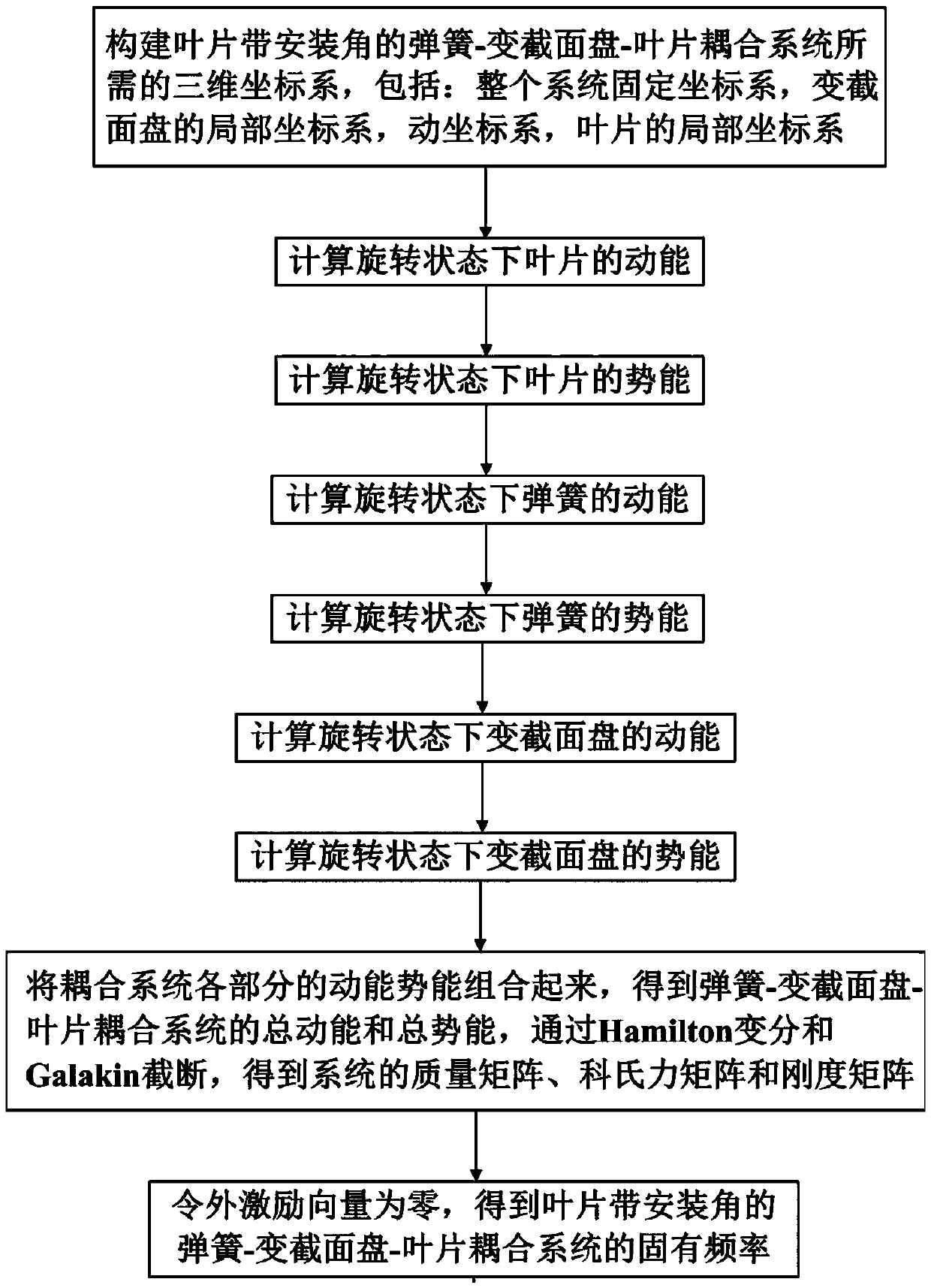
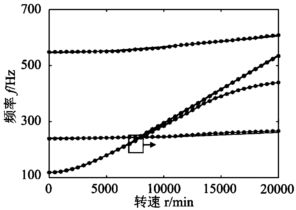
[0141] A dynamic modeling method for a spring-variable cross-section disc-blade coupling system with blade installation angle, such as figure 1 As shown in the figure, the changes of the first-order and second-order frequencies of the blade and disk with the rotating speed are respectively shown in the figure. The intersection point of the frequency is the resonant frequency, so the rotating speed of the resonant point frequency should be avoided. Specifically, the method includes the following steps:

[0142] Step 1: Construct a three-dimensional coordinate system required for dynamic modeling of a spring-variable cross-section disc-blade coupling system with a vane installation angle, including: the fixed coordinate system OXYZ of the entire coupling system, and the coordinate system ox of the variable cross-section disc d the y d z d , the moving coordinate system ox of the whole system during the motion process r the y r z r , the local coordinate system ox of th...

Embodiment 2

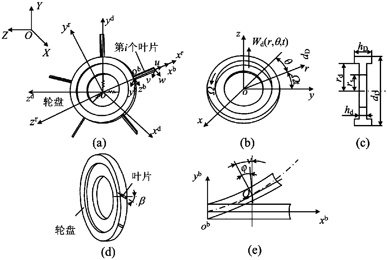
[0267] In this embodiment, the schematic diagram of the spring-variable cross-section disk-blade coupling system with the blade having an installation angle is as follows figure 2 As shown, figure 2 Among them, (a) represents the dynamic model of the spring-variable cross-section disk-vane coupling system, (b) represents the coordinates of the variable cross-section rotating disk, (c) is the cross-sectional view of (b), indicating the geometric dimensions of the variable cross-section disk, ( d) represents the installation angle of the blade on the variable-section rotating disk, and (e) represents the schematic diagram of the blade in the local coordinate system. The modeling method of spring-variable cross-section disk-vane coupling system with blades with installation angle includes the following steps:

[0268] Step 1: Obtain the structural parameters and material parameters of the spring-variable cross-section disc-blade coupling system with the installation angle of t...


PUM


Abstract

The invention relates to a spring. Variable section disk Dynamic modeling method of blade system using variable cross-section disk The centrifugal stiffening, rotational softening and Coriolis forceeffects of the whole coupled system are considered simultaneously. The invention can save the experiment cost, and can be used to obtain different dynamic models only by changing the size and blanking parameters of the blade and the variable cross-section disk as well as the rigidity of the spring. At the same time, the accuracy and convenience of the results obtained by this dynamic model can beanalyzed by comparing with the natural frequencies obtained by commercial finite element software. Compared with the commercial finite element software, the semi-analytical method of the invention isadopted for modeling, the degree of freedom of the model is less, and the computational efficiency is higher. In addition, through the analysis of different rotational speed of the spring Variable section disk The dynamic frequency of the blade coupling system can effectively avoid the resonant frequency and reasonably select the working speed to make the system work more stably.

Description

technical field [0001] The invention relates to a dynamic modeling method of a spring-variable cross-section disc-blade system, belonging to the technical field of mechanical dynamics. Background technique [0002] At present, the existing spring-disk-blade modeling methods mainly include the following methods: [0003] 1. Based on commercial finite element analysis software [0004] Import the CAD 3D model into the commercial finite element analysis software or directly build the 3D model in the finite element software, select the appropriate unit and material parameters, mesh the 3D model, establish the finite element model, set the appropriate constraints and select A suitable solution method is used to analyze the dynamic characteristics of the spring-variable cross-section disc-vane system. However, when using the existing commercial finite element analysis software to analyze the dynamic characteristics of the spring-variable cross-section disc-vane system with insta...

Claims


Application Information

Patent Timeline
IPC IPC(8): G06F17/50
CPCG06F30/17G06F30/23
Inventor 马辉刘诗宇崔璨曾劲杨桐
Owner NORTHEASTERN UNIV
Why Eureka
Try Eureka