Cast sand core efficient manufacturing equipment
A technology for manufacturing equipment and foundry sand, which is applied in the field of high-efficiency manufacturing equipment for foundry sand cores, can solve problems such as low production efficiency, and achieve the effects of reducing time, reducing dust flying, and improving processing efficiency
- Summary
- Abstract
- Description
- Claims
- Application Information
AI Technical Summary
Problems solved by technology
Method used
Image

Examples
Embodiment 1
[0039] Embodiments of the present invention are described in detail below, examples of which are shown in the drawings, wherein the same or similar reference numerals designate the same or similar elements or elements having the same or similar functions throughout. The embodiments described below by referring to the figures are exemplary and are intended to explain the present invention and should not be construed as limiting the present invention.
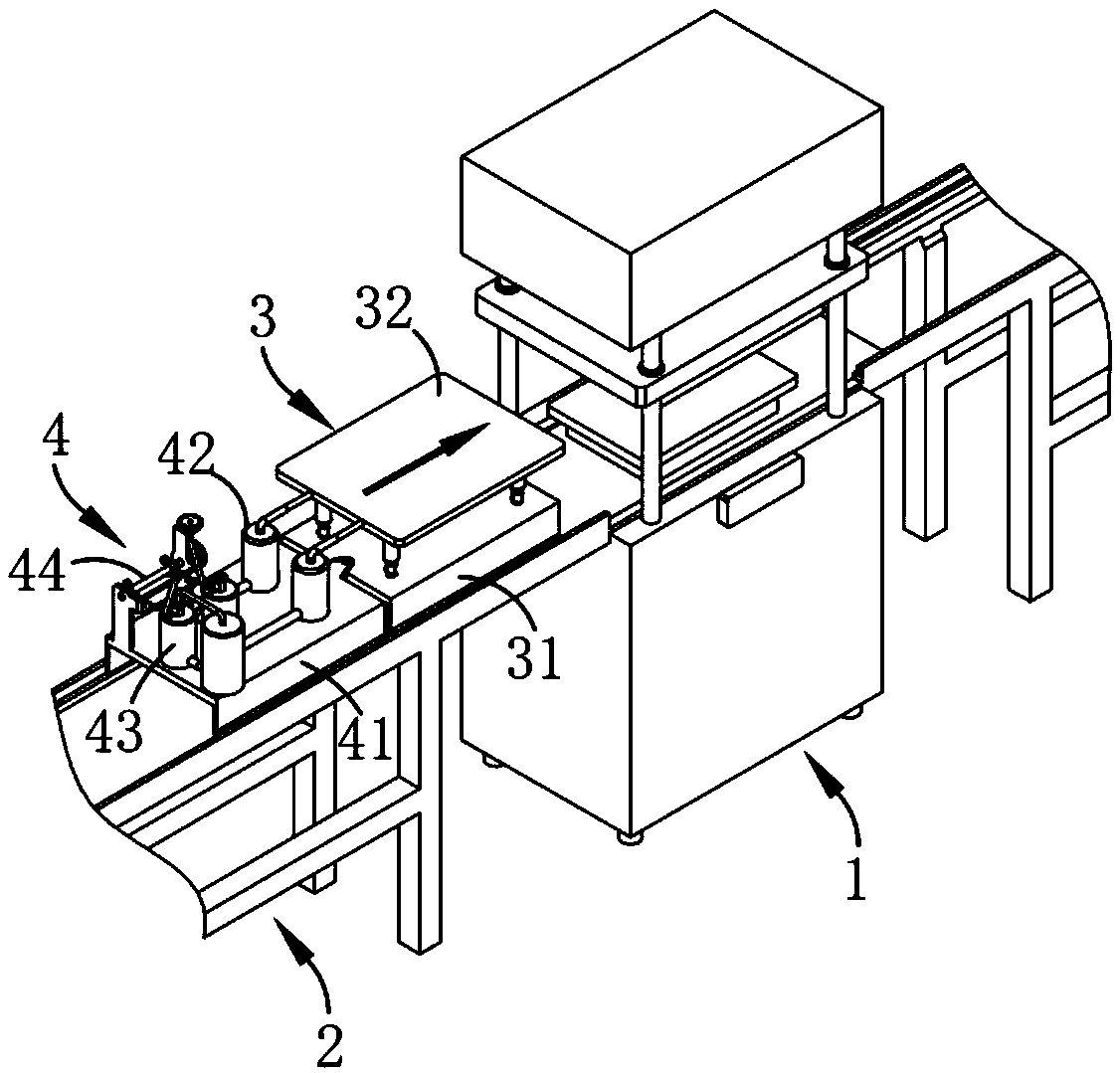
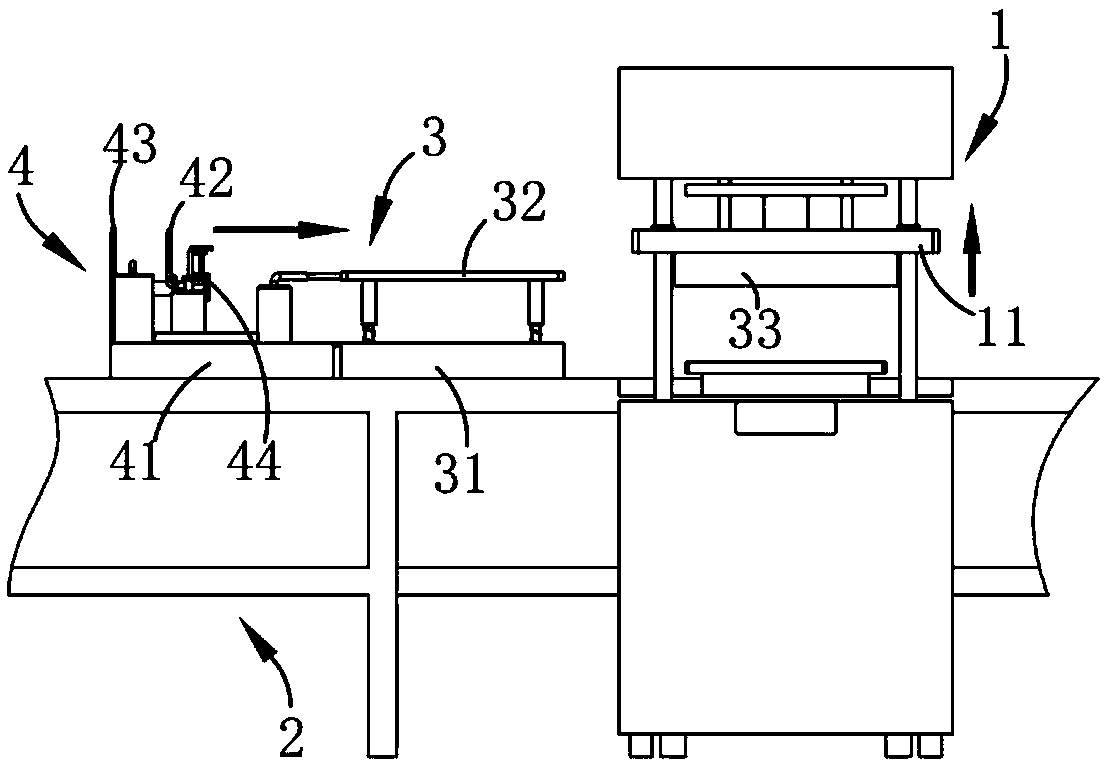
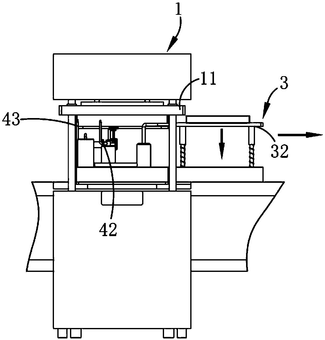
[0040] Such as figure 1 , 2 , 3 and 4, a casting sand core efficient manufacturing equipment, including a core shooter 1, also includes:
[0041] A guide mechanism 2, the guide mechanism 2 is respectively located in the front and rear sections of the core shooting machine 1 and connected to it; in this embodiment, the material receiving mechanism 3 moves along the guide mechanism 2 through the core shooter 1;
[0042] The material receiving mechanism 3, the material receiving mechanism 3 moves along the guide mechanism 2, which...
Embodiment 2
[0047] Such as figure 1 , 2 As shown in and 6, the same or corresponding parts as in the first embodiment adopt the corresponding reference numerals of the first embodiment. For the sake of simplicity, only the differences from the first embodiment are described below; the second embodiment and the first embodiment The difference is that: the receiving assembly 32 includes a plurality of guide posts 321 arranged vertically and parallel on the upper surface of the moving trolley 31 , and the guide posts 321 are slidably arranged in the vertical direction and arranged horizontally. The receiving portion 322 of the state and the elastic portion 323 arranged between the receiving portion 322 and the moving trolley 31; While the receiving part 322 is limited by the guide column 321, the receiving part 322 is pulled by the elastic part 323 to improve the stability during its upward movement. At the same time, the receiving part 322 is detached from the connecting assembly 33 and fa...
Embodiment 3
[0052] Such as Figure 8 , 9 As shown in and 10, the parts identical or corresponding to those in the second embodiment adopt the reference numerals corresponding to the second embodiment. For the sake of simplicity, only the differences from the first embodiment are described below; The difference is that the removal assembly 42 includes an air storage chamber 421, a compression chamber A422 communicated with the air storage chamber 421, a compression disk A423 arranged in the compression chamber A422 and fixedly connected with the receiving assembly 32, Rotate the air nozzle A424 that is arranged on the air storage chamber 421 and communicates with its interior, and the air intake valve 425 that is arranged on the top of the air storage chamber 421 for air to enter; in this embodiment, the air intake valve 425 is a one-way valve Setting, when the receiving part 321 moves up, it drives the compression disc A423 to move through the intake valve 425 to fill the gas storage cha...
PUM
 Abstract
Description
Claims
Application Information
 - R&D
- Intellectual Property
- Life Sciences
- Materials
- Tech Scout
- Unparalleled Data Quality
- Higher Quality Content
- 60% Fewer Hallucinations
Browse by: Latest US Patents, China's latest patents, Technical Efficacy Thesaurus, Application Domain, Technology Topic, Popular Technical Reports.
© 2025 PatSnap. All rights reserved.Legal|Privacy policy|Modern Slavery Act Transparency Statement|Sitemap|About US| Contact US: help@patsnap.com