
Die-casting die structure

A die-casting mold and insert technology, which is applied in the field of mold structure, can solve the problems of difficult processing, time-consuming, high precision requirements, etc., and achieve the effects of reducing processing difficulty, facilitating processing, and simple structure

Pending Publication Date: 2018-11-30
KOLBENSCHMIDT PIERBURG SHANGHAI NONFERROUS COMPONENTS
View PDF8 Cites 0 Cited by
  • Summary
  • Abstract
  • Description
  • Claims
  • Application Information

AI Technical Summary

Problems solved by technology

However, the point-to-point cooling waterway requires high precision for deep hole machining, which is difficult to process, and the cleaning and maintenance of the cooling waterway is also troublesome and time-consuming
In addition, the point-to-point cooling water circuit is still difficult to ensure the heat balance on the surface of the die-casting mold, thus affecting the cooling effect of the die-casting mold

Method used


Image

  • Die-casting die structure
  • Die-casting die structure
  • Die-casting die structure

Examples


Embodiment Construction

[0028] The specific implementation manners of the present invention will be described in further detail below in conjunction with the accompanying drawings. These embodiments are only used to illustrate the present invention, not to limit the present invention.

[0029] In the description of the present invention, it should be noted that the orientation or positional relationship indicated by the terms "upper", "lower", etc. is based on the orientation or positional relationship shown in the drawings, and is only for the convenience of describing the present invention and simplifying the description. It is not intended to indicate or imply that the referred device or element must have a particular orientation, be constructed in a particular orientation, and operate in a particular orientation, and thus should not be construed as limiting the invention. In addition, the terms "first" and "second" are used for descriptive purposes only, and should not be understood as indicating...


PUM


Abstract

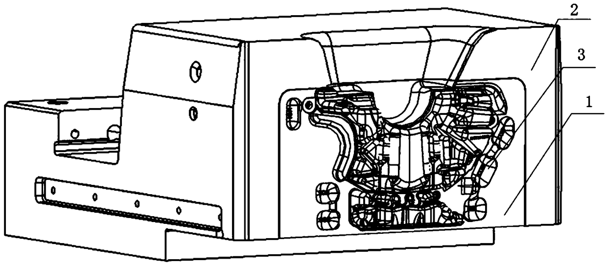
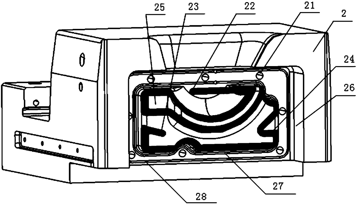
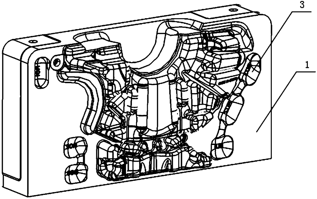
The invention provides a die-casting die structure. The die-casting die structure comprises an insert and a base. A raised cavity face is arranged on the front side of the insert. A sunk cavity is formed at the position, corresponding to the raised cavity face, of the reverse side of the insert. A groove is formed in the base. The insert is embedded into the groove. A boss fits with the cavity onthe reverse side of the insert is arranged on the bottom face of the groove. A continuous groove is formed in the surface of the boss. The continuous groove occupies the spatial range of the whole boss in twists and turns. When the boss fits with the cavity on the reverse side of the insert, a continuous cooling water route is formed by the continuous groove. The die-casting die structure has thebeneficial effects that the structure is simple; machining is convenient; the cooling water route is reasonably and uniformly distributed on the surface of the base; thus deep hole machining is not needed to be conducted; machining difficulty is lowered; and the shape of the cooling water route can be designed according to the position and size of the cavity face, and full cooling of products in contact with the cavity face is guaranteed.

Description

technical field [0001] The invention relates to a mold structure, in particular to a die-casting mold structure. Background technique [0002] With the development of high-pressure casting technology, more and more types of aluminum alloy castings are produced, and the size of the products is also increasing. The size of the die-casting mold is also increasing, and the cooling requirements for the die-casting mold are also more stringent. . The cooling methods of inserts in existing die-casting molds are mainly based on diaphragm cooling and core cooling, and most of them are equipped with point-to-point cooling water channels. However, the point-to-point cooling waterway requires high precision for deep hole machining, which is difficult to process, and it is troublesome and time-consuming to clean and maintain the cooling waterway. In addition, the point-to-point cooling water channel is still difficult to ensure the heat balance on the surface of the die-casting mold, t...

Claims


Application Information

Patent Timeline
IPC IPC(8): B22D17/22B22D17/24
CPCB22D17/2218B22D17/24
Inventor 沈明强黄荣发张宇皓侯叶峰
Owner KOLBENSCHMIDT PIERBURG SHANGHAI NONFERROUS COMPONENTS
Learn More