Disk shear

A disc shear and disc technology, which is applied in the field of metallurgical manufacturing, can solve the problems of low surface quality of the strip, uneven force on the upper cutter shaft assembly, skew, etc., and achieve the effect of improving the cutting quality of the strip.

Pending Publication Date: 2018-11-30
XIANGYANG YUQING TRANSMISSION TECH
View PDF1 Cites 0 Cited by
  • Summary
  • Abstract
  • Description
  • Claims
  • Application Information

AI Technical Summary

Problems solved by technology

[0004] Although the side gap adjustment mechanism disclosed above can realize the adjustment of the side gap, since it has only one linear guide rail set horizontally, if the linear guide rail pair is arranged on one side of the axis of the upper cutter shaft, the upper cutter shaft will The component is heavy, and when it is adjusted to the upper cutter shaft, it is easy to cause the upper cutter shaft assembly to be skewed due to uneven force; , the main drive motor can only drive the rotation of the lower knife shaft assembly, the lower knife shaft actively cuts the strip, and the upper knife shaft rotates passively during the shearing process, but the surface quality of the strip cut out in this way is low and easy to produce quality problems

Method used


Image

  • Disk shear
  • Disk shear
  • Disk shear

Examples


Embodiment Construction

[0029] The technical solutions of the present invention will be clearly and completely described below in conjunction with specific embodiments. Apparently, the described embodiments are only some of the embodiments of the present invention, not all of them. Based on the embodiments of the present invention, all other embodiments obtained by persons of ordinary skill in the art without creative efforts fall within the protection scope of the present invention.

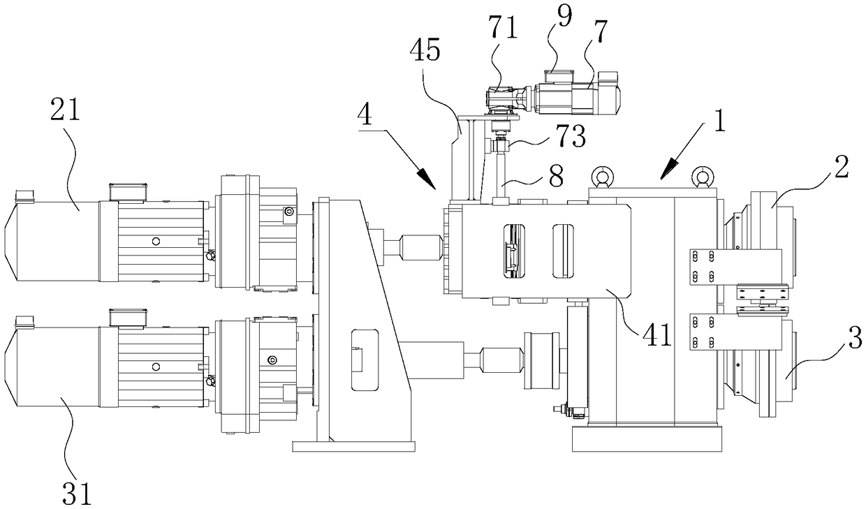
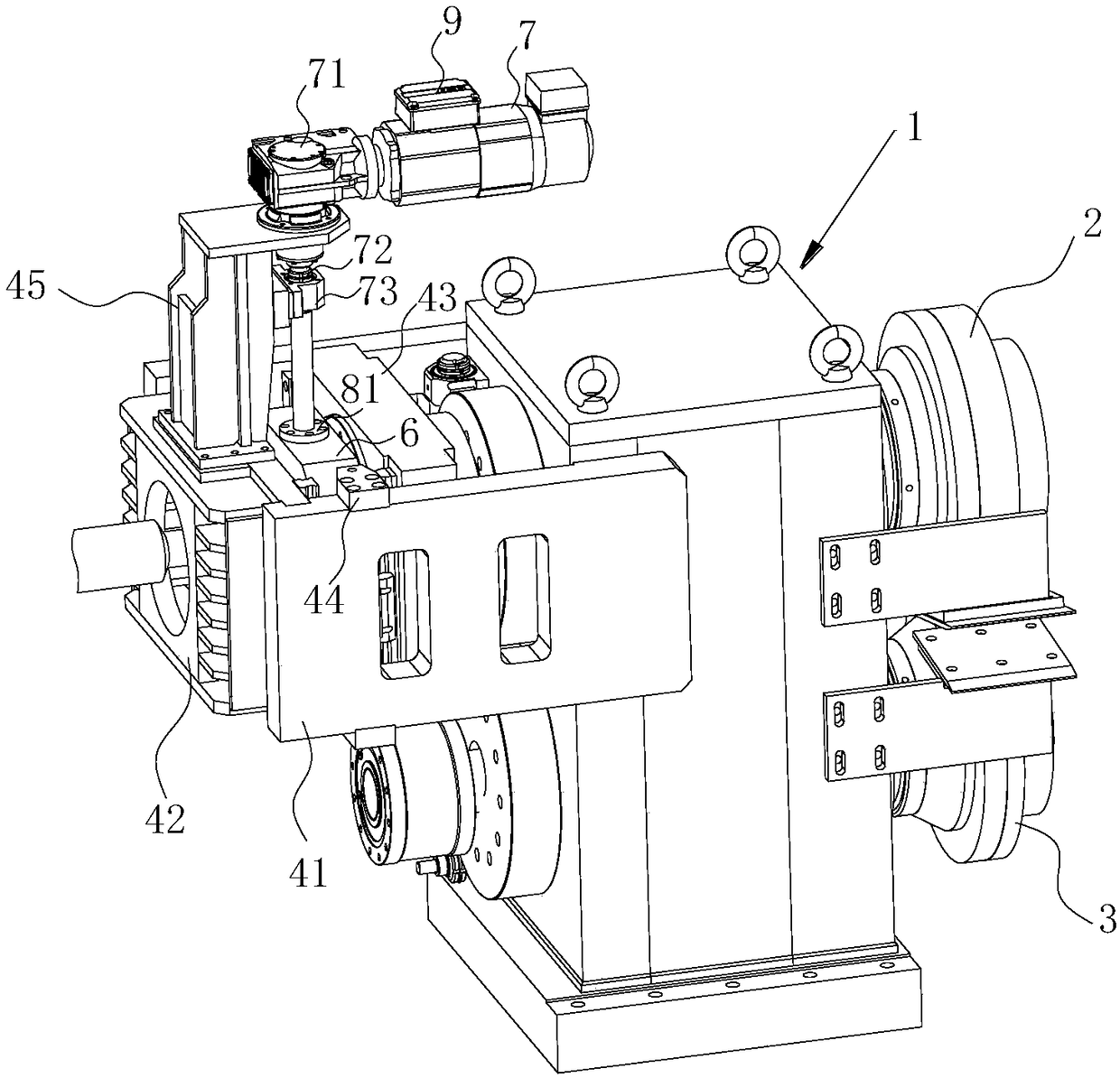
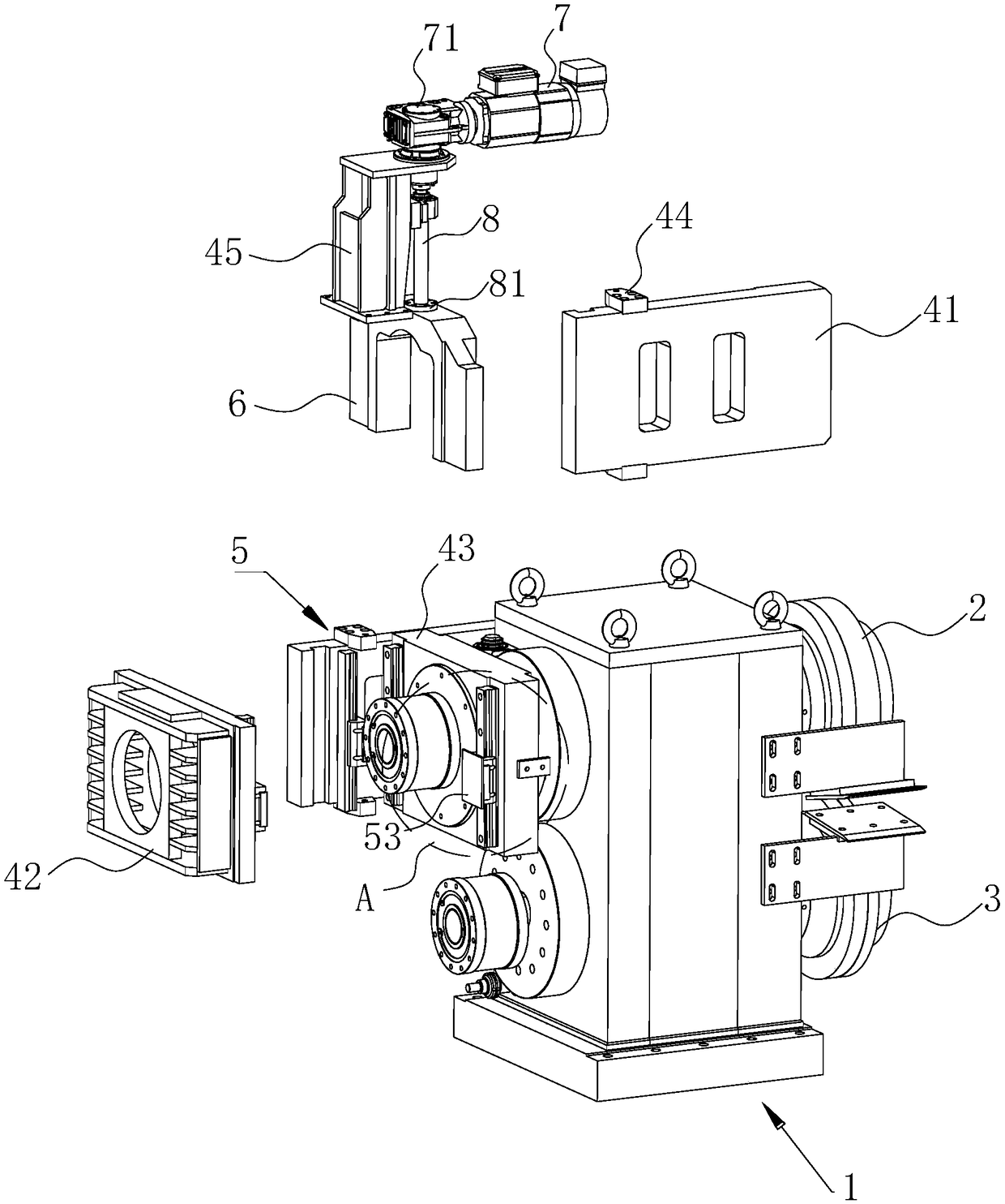
[0030] A kind of disc shears, refer to figure 1 , including a disc scissors box 1 for supporting the cutter shaft assembly, an upper cutter shaft assembly 2 and a lower cutter shaft assembly 3 set through the disc scissors box 1, wherein the upper cutter shaft assembly 2 and the lower cutter shaft assembly 3 can The relative disk scissors box 1 moves to facilitate the adjustment of the side gap and the overlapping amount between the two sets of cutter shafts. The specific connection method is known to those skilled in...


PUM


Abstract

The invention relates to the technical field of metallurgy manufacturing, in particular to a disk shear. The backlash adjusting function is achieved, meanwhile, active rotating of an upper tool shaftassembly can be achieved, and the upper tool shaft assembly and a lower tool shaft assembly each have drive power so as to improve the shear quality of a plate and strip. The disk shear is technicallycharacterized in that the disk shear comprises a disk shear box, the upper tool shaft assembly, the lower tool shaft assembly, a lower transmission motor in transmission connection with the lower tool shaft assembly and an upper transmission motor which is located above the lower transmission motor and is in transmission connection with the upper tool shaft assembly, wherein the upper tool shaftassembly and the lower tool shaft assembly penetrate through the disk shear box; a backlash adjusting device is arranged on the side, close to the upper transmission motor, of the upper tool shaft assembly and mainly comprises a U-shaped nut sleeve mounting plate and a backlash adjusting motor driving the U-shaped nut sleeve mounting plate to move; and wedge blocks, a C-shaped sliding block and alinear guide rail are arranged on the side wall of the U-shaped nut sleeve mounting plate, the C-shaped sliding block and the linear guide rail can relatively slide, and backlash adjustment is achieved through movement of the C-shaped sliding block and cooperation of the wedge blocks.

Description

technical field [0001] The invention belongs to the technical field of metallurgical manufacturing, in particular to a disc shear. Background technique [0002] In modern cold-rolled thin plate production lines and hardcover lines, high-precision disc shears are generally configured to perform longitudinal trimming of steel plates. During the working process, it is necessary to adjust the overlapping amount and the side gap between the upper and lower cutter heads of the disc shears according to the actual situation, and the accuracy of the side clearance adjustment mechanism of the disc shears directly affects the edge quality of the sheared steel plate. [0003] The utility model patent with the authorized announcement number CN202052979U discloses an adjustment mechanism for the side clearance of the disc scissors, including a drive motor, a coupling, a bearing seat, an upper cutter head, an upper cutter shaft, a lower cutter head, and a thrust bearing. A pair of linear ...

Claims


Application Information

Patent Timeline
IPC IPC(8): B23D19/04B23D33/00B23Q5/10
CPCB23D19/04B23D33/00B23Q5/10
Inventor 李飞吴凯庄素文刘明云李海涛
Owner XIANGYANG YUQING TRANSMISSION TECH
Why Eureka
Try Eureka