
Radial friction welding process method for connecting austenitic alloy steel and non-magnetic drill collar

A non-magnetic drill collar and friction welding technology, applied in welding equipment, metal processing equipment, applications, etc., can solve problems such as low production efficiency, high cost, and difficult repair of failed drill collars, and achieve the effect of avoiding impact

Inactive Publication Date: 2018-11-30
SHANDONG UNIV
View PDF5 Cites 15 Cited by
  • Summary
  • Abstract
  • Description
  • Claims
  • Application Information

AI Technical Summary

Problems solved by technology

The present invention proposes to process and repair non-magnetic drill collars with continuous drive radial friction welding process and inertial radial friction welding process, so as to improve the problems of material waste, high cost and low production efficiency caused by existing processing methods. And overcome the problem that the failed drill collar is difficult to repair

Method used


Image

  • Radial friction welding process method for connecting austenitic alloy steel and non-magnetic drill collar
  • Radial friction welding process method for connecting austenitic alloy steel and non-magnetic drill collar
  • Radial friction welding process method for connecting austenitic alloy steel and non-magnetic drill collar

Examples


Embodiment 1

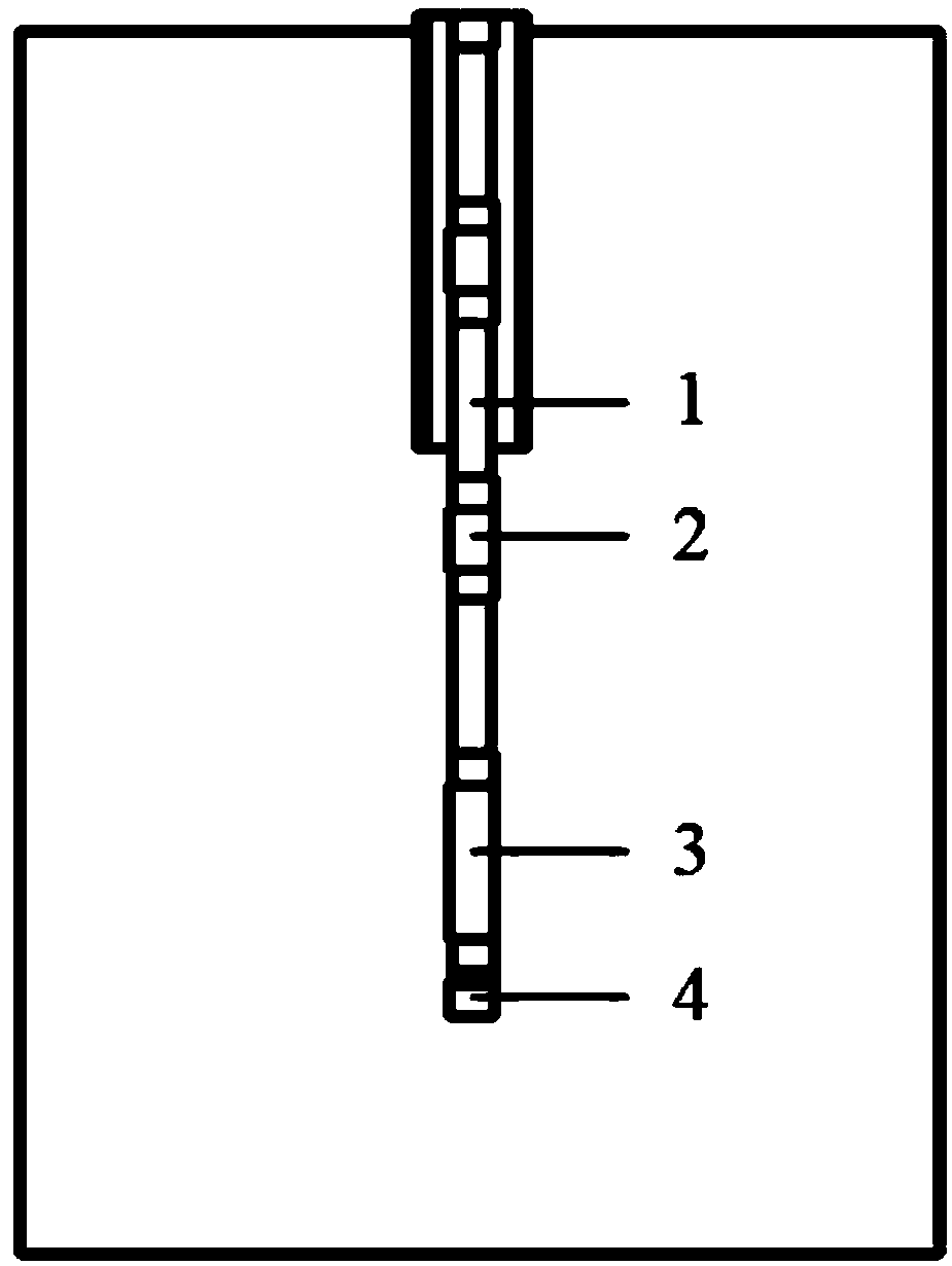
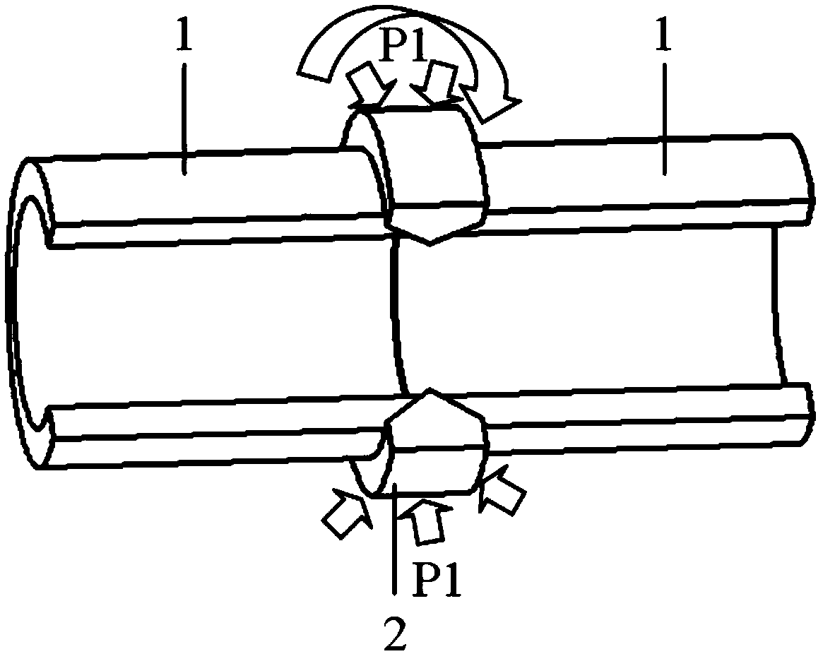
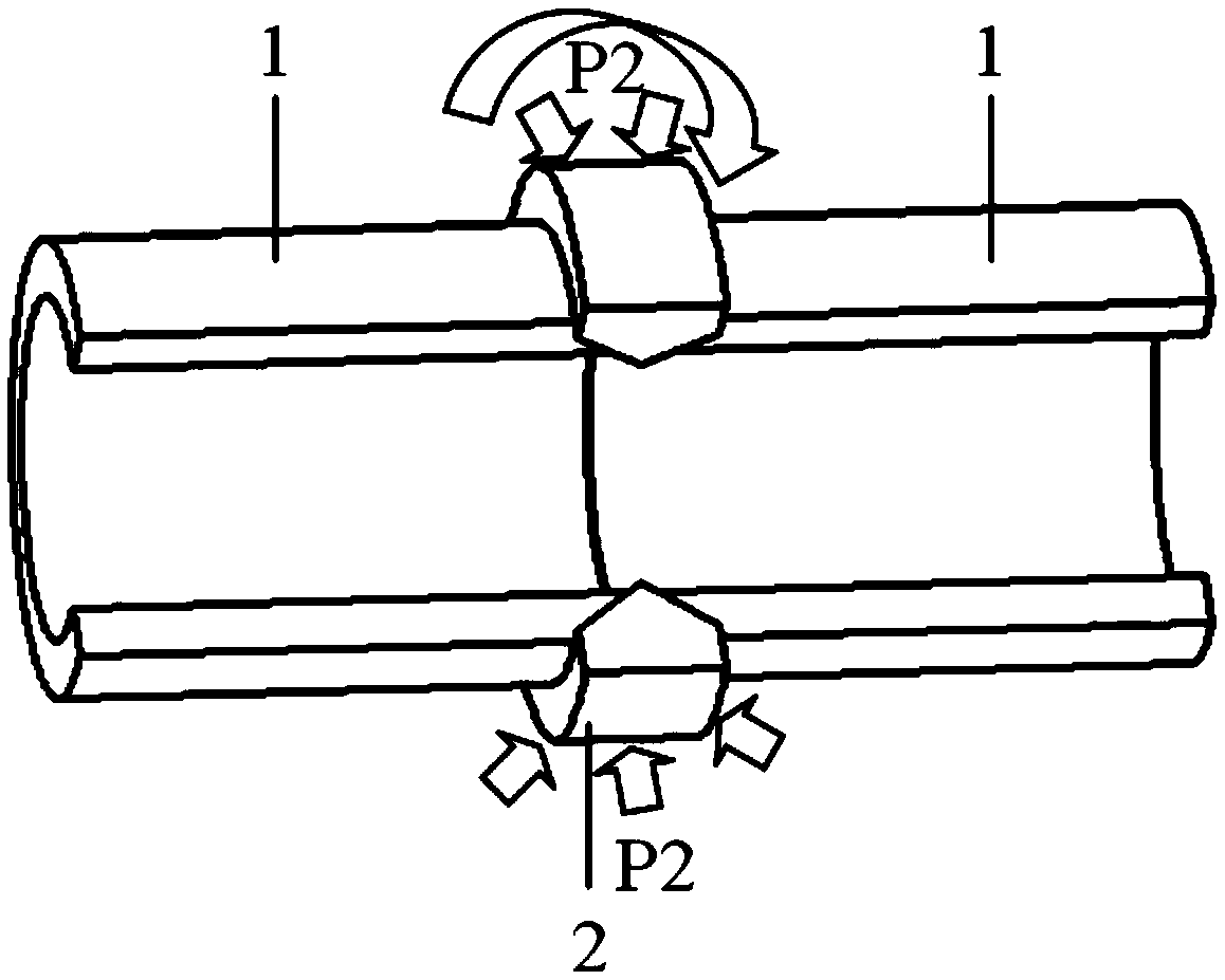
[0069] like Figure 2-5 As shown, a method for preparing non-magnetic drill collars by continuous drive radial friction welding comprises the following steps:

[0070] (1) Welding interface treatment: Austenitic alloy steel (composition as shown in Table 1) is made into a workpiece with an outer diameter of φ104.8mm, a wall thickness of δ=20mm, and a length of 300mm, and such as Figure 5 The radial ring shown, where the pipe end surface bevel angle α = 30°, such as Figure 4 As shown, the sharp angle at the front end of the radial ring is the same as the V-shaped groove and completely coincides with the groove. The specific dimensions of the radial ring used are x=30mm, y=10mm, z=20mm. Use sandpaper to clean the surface of the workpiece to be welded. At the same time, use alcohol and acetone to remove oil stains on the interface to be welded;

[0071] (2) Weldment clamping: the workpiece 1 and radial ring 2 in step (1) are clamped into the pipe body fixture in the HSMZ-130 ...

Embodiment 2

[0074] like Figure 2-5 As shown, a method for preparing non-magnetic drill collars by inertial radial friction welding, the main difference between it and the continuous drive radial friction welding process is that the driving device stops the flywheel and radial ring after the flywheel and radial ring reach a predetermined speed. Driven to the ring, using the flywheel and the inertial rotation of the radial ring to achieve friction welding. The method comprises the steps of:

[0075] (1) Welding interface treatment: Austenitic alloy steel (composition shown in Table 1) is made into a workpiece with a specification of φ228.6mm, a wall thickness of δ80mm, and a length of 300mm. Figure 5 The radial ring shown, where the pipe end surface bevel angle α = 30°, such as Figure 4As shown, the sharp angle at the front end of the radial ring is the same as the V-shaped groove and completely coincides with the groove. The specific dimensions of the radial ring used are x=50mm, y=20...

Embodiment 3

[0079] The preparation method is the same as in Example 1, except that the spindle speed is 2500 rad / min, the friction pressure is 50 MPa, the friction time is 15 s, the upsetting pressure is 600 MPa, and the holding time is 15 s.


PUM

PropertyMeasurementUnit
Tensile strengthaaaaaaaaaa
Yield strengthaaaaaaaaaa

Abstract

The invention relates to a radial friction welding process method for connecting austenitic alloy steel and a non-magnetic drill collar, and belongs to the field of preparation of oil and gas drillingtools. The radial friction welding process method comprises the following steps: clamping a workpiece made of the austenitic alloy steel and a radial ring into a fixture of a friction welding machine, and then welding the workpiece in the fixture; at the beginning of welding, rotating the radial ring, and applying frictional pressure to the radial ring along the radial direction thereof to drivethe radial ring and the welded workpiece to make relative movement and friction to generate heat; when a friction interface and metal in the vicinity thereof reach a thermoplastic state, stopping applying the friction pressure under certain conditions, and applying upset pressure to the radial ring and keeping the pressure; and unloading the upset pressure and then taking out the workpiece, so asto obtain the non-magnetic drill collar. In the method, the non-magnetic drill collar is machined and repaired by the radial friction welding method, so as to solve the problems of material waste, high cost and low production efficiency of existing processing methods, and overcome the problem that a failed drill collar is difficult to repair.

Description

technical field [0001] The invention belongs to the application field of radial friction welding technology, and specifically relates to the application of radial friction welding technology and inertia radial friction welding technology in high-nitrogen austenitic alloy steel and non-magnetic drill collars. Background technique [0002] In recent decades, the drilling depth of oil and gas fields has been increasing. In order to ensure sufficient vertical drilling accuracy, it is necessary to equip a Measurement While Drilling (MWD) device during the drilling process. The accuracy is corrected to ensure the accuracy of the vertical well drilling direction, so the measurement while drilling device must work in a non-magnetic environment. However, most of the drilling tools are magnetic, which in turn generates a magnetic field, which affects the magnetic measuring instrument and affects the accuracy of the measurement-while-drilling device. The non-magnetic drill collar can c...

Claims


Application Information

Patent Timeline
IPC IPC(8): B23K20/12C22C38/58C22C38/42C22C38/44C22C38/46C22C38/02C22C38/06B23K101/04
CPCB23K20/1225B23K20/129C22C38/001C22C38/02C22C38/06C22C38/42C22C38/44C22C38/46C22C38/58
Inventor 秦国梁杨帆
Owner SHANDONG UNIV
Learn More