Clamp for sawing motor swash plate and production line

A swash plate and sawing technology, which is applied in the direction of clamping, manufacturing tools, supports, etc., can solve the problems of serious consumption of raw materials and difficulty in meeting design requirements, and achieve the effects of simple structure, high sawing precision, and reduced production costs

Pending Publication Date: 2018-11-30
杭州力龙液压有限公司
View PDF0 Cites 1 Cited by
  • Summary
  • Abstract
  • Description
  • Claims
  • Application Information

AI Technical Summary

Problems solved by technology

[0002] In the machining stage, due to the precise angle of the shape plane of the motor swash plate, it is difficult

Method used


Image

  • Clamp for sawing motor swash plate and production line
  • Clamp for sawing motor swash plate and production line
  • Clamp for sawing motor swash plate and production line

Examples


Embodiment 1

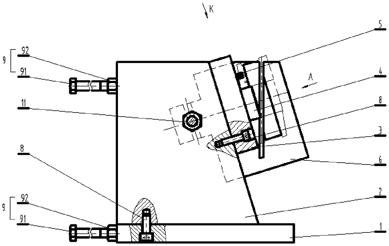
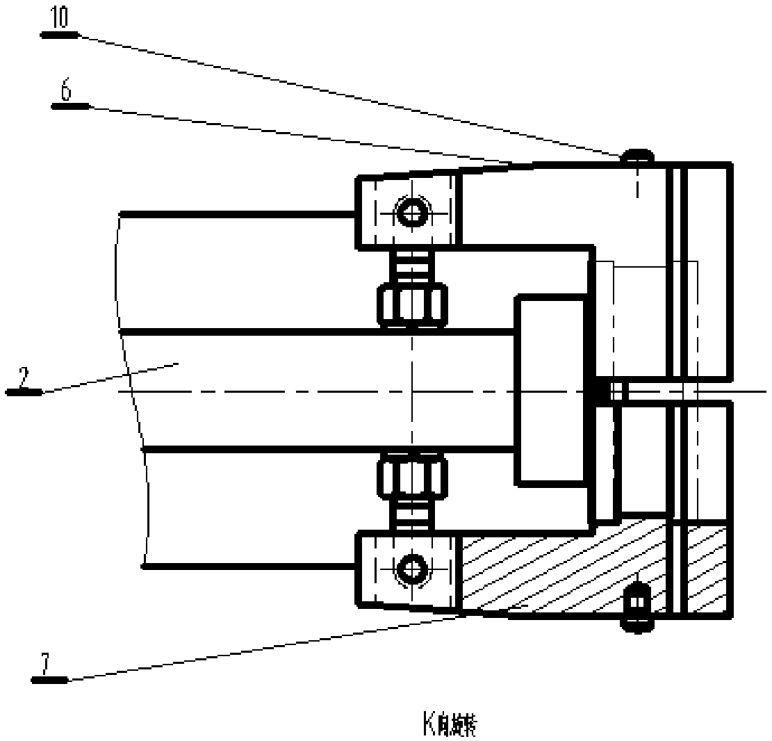
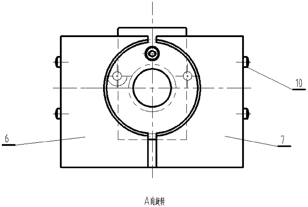
[0028] figure 1 Schematic diagram of the structure of the jig for motor swash plate sawing provided in Embodiment 1 of the present invention; figure 2 Yes figure 1 Middle K direction view; image 3 Yes figure 1 Middle A view; such as Figure 1-Figure 3 As shown, the jig for motor swash plate sawing provided by Embodiment 1 of the present invention includes a base plate 1, a stand plate 2 and a positioning plate 3;

[0029] The stand plate 2 is installed on the base plate 1, the positioning plate 3 is installed on the stand plate 2, the positioning pin 4 and the orientation pin 5 are respectively installed on the positioning plate 3, the positioning pin 4 and the The directional pin 5 is used to determine the center position of the cylindrical part and prevent its circumferential movement. A left clamping block 6 and a right clamping block 7 are respectively hinged on the standing plate 2 on both sides of the positioning plate 3 .

[0030] The jig for motor swash plate sa...

Embodiment 2

[0034] The jig for motor slanting disk sawing provided in the second embodiment is a further improvement on the jig for motor slanting disk sawing provided in the first embodiment. In the first embodiment and Figure 1-Figure 3 On the basis of the motor swash plate sawing jig provided in the second embodiment, it includes a bottom plate 1, a stand plate 2 and a positioning plate 3;

[0035] The stand plate 2 is installed on the base plate 1, the positioning plate 3 is installed on the stand plate 2, the positioning pin 4 and the orientation pin 5 are respectively installed on the positioning plate 3, the positioning pin 4 and the The directional pin 5 is used to determine the center position of the cylindrical part and prevent its circumferential movement. A left clamping block 6 and a right clamping block 7 are respectively hinged on the standing plate 2 on both sides of the positioning plate 3 .

[0036] The jig for motor swash plate sawing provided by the present invention ...

Embodiment 3

[0041] The jig for motor slanting disk sawing provided in the third part of this embodiment is a further improvement on the jig for motor slanting disk sawing provided in the first embodiment. In the first embodiment and Figure 1-Figure 3 On the basis of the motor swash plate sawing jig provided in the third embodiment, it includes a base plate 1, a stand plate 2 and a positioning plate 3;

[0042] The stand plate 2 is installed on the base plate 1, the positioning plate 3 is installed on the stand plate 2, the positioning pin 4 and the orientation pin 5 are respectively installed on the positioning plate 3, the positioning pin 4 and the The directional pin 5 is used to determine the center position of the cylindrical part and prevent its circumferential movement. A left clamping block 6 and a right clamping block 7 are respectively hinged on the standing plate 2 on both sides of the positioning plate 3 .

[0043] The jig for motor swash plate sawing provided by the present i...


PUM


Abstract

The invention discloses a clamp for sawing a motor swash plate. The clamp comprises a bottom plate, a station plate and a positioning plate. The station plate is installed on the bottom plate, the positioning plate is installed on the station plate, a positioning pin and a directional pin are installed on the positioning plate, the positioning pin and the directional pin are used for determining the central position of a cylindrical part and preventing the cylindrical part from moving in the circumferential direction, and the portions, on the two sides of the positioning plate, of the stationplate are correspondingly hinged with a left clamping block and a right clamping block. The clamp has the beneficial effects of being simple in structure, high in sawing precision, easy and convenientto use and capable of improving the angular precision of the inclined plane of the part to a certain extent and reducing the production cost. According to the clamp, the clamp is fixed by a hydraulicmechanism of a sawing machine, the central position of the cylindrical part is determined through the positioning pin and the directional pin on the clamp, and the circumferential movement of the cylindrical part is prevented; in addition, the left clamping block and the right clamping block are adopted to prevent the radial movement of the part, so that displacement does not occur in the sawingprocess of the part; the design of the left clamping block and the right clamping block ensures that the sawing position of a saw blade is accurate, and the angle of the part can be ensured; and on this basis, the invention further provides a production line.

Description

technical field [0001] The invention relates to a fixture and a production line for motor swash plate sawing. Background technique [0002] In the machining stage, due to the precise angle of the shape plane of the motor swash plate, it is difficult to meet the design requirements by using traditional turning methods, and the consumption of raw materials is serious. Contents of the invention [0003] The purpose of the present invention is to provide a jig for motor swash plate sawing, so as to solve the above-mentioned technical problems existing in the prior art. [0004] The jig for motor swash plate sawing provided by the present invention includes a bottom plate, a stand plate and a positioning plate; [0005] The stand plate is installed on the base plate, the positioning plate is installed on the stand plate, and a positioning pin and an orientation pin are respectively installed on the positioning plate, and the positioning pin and the orientation pin are used to ...

Claims


Application Information

Patent Timeline
IPC IPC(8): B23Q3/06
CPCB23Q3/062
Inventor 曹国丰吴新锋曹祝兵
Owner 杭州力龙液压有限公司
Why Eureka
Try Eureka