
Novel automatic clothes hanger and assembling method thereof

An automatic technology for clothes drying racks, applied in the field of clothes drying racks, can solve the problems of increasing the transportation cost of automatic clothes drying racks, difficult to change the volume, and difficult to dry clothes.

Pending Publication Date: 2018-11-30
宁波斯洛曼智能科技有限公司
View PDF7 Cites 3 Cited by
  • Summary
  • Abstract
  • Description
  • Claims
  • Application Information

AI Technical Summary

Problems solved by technology

The clothes hanger 3A not only increases the volume of the clothes hanger 40A, but the width of the clothes hanger 3A is greater than or equal to the width of the clothes hanger 40A. Even if the clothes hanger 32A is stored, the volume of the clothes hanger 3A is difficult to change. During transportation, the clothes hanger 3A increases the transportation space, which also increases the transportation cost of each automatic clothes drying rack
Moreover, because there is no clothes hanging hole on the secondary pole, the clothes hanger hanging on the secondary pole is easy to fall, which affects the use of drying, and the drying function of the secondary pole cannot be fully exerted, and this is a problem that the round tube cannot solve
[0003] On the other hand, since the volume of the hanging holes is fixed, the spacing between the hanging holes will directly affect the drying effect, and the thickness of the clothes in the four seasons is even more different. For example, the space required for drying winter clothes and summer clothes is very different. same
If the distance between the hanging holes is too small, the summer clothes may be dry, but the winter clothes are too crowded, making it more difficult to dry the winter clothes and prolong the drying time; if the distance between the hanging holes is too large, it may It is suitable for drying clothes in winter, but the number of clothes that can be dried is relatively small, and the laundry in spring and summer is more frequent, and there are more clothes to be dried, resulting in insufficient space for drying

Method used


Image

  • Novel automatic clothes hanger and assembling method thereof
  • Novel automatic clothes hanger and assembling method thereof
  • Novel automatic clothes hanger and assembling method thereof

Examples


Embodiment Construction

[0037] The following description serves to disclose the present invention to enable those skilled in the art to carry out the present invention. The preferred embodiments described below are only examples, and those skilled in the art can devise other obvious variations.

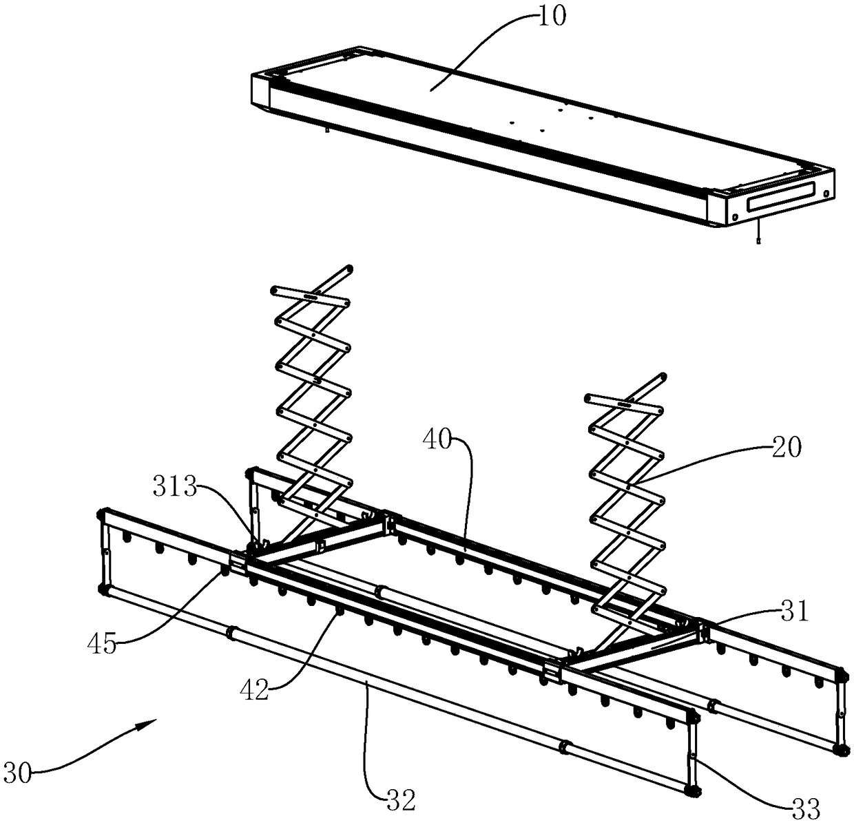
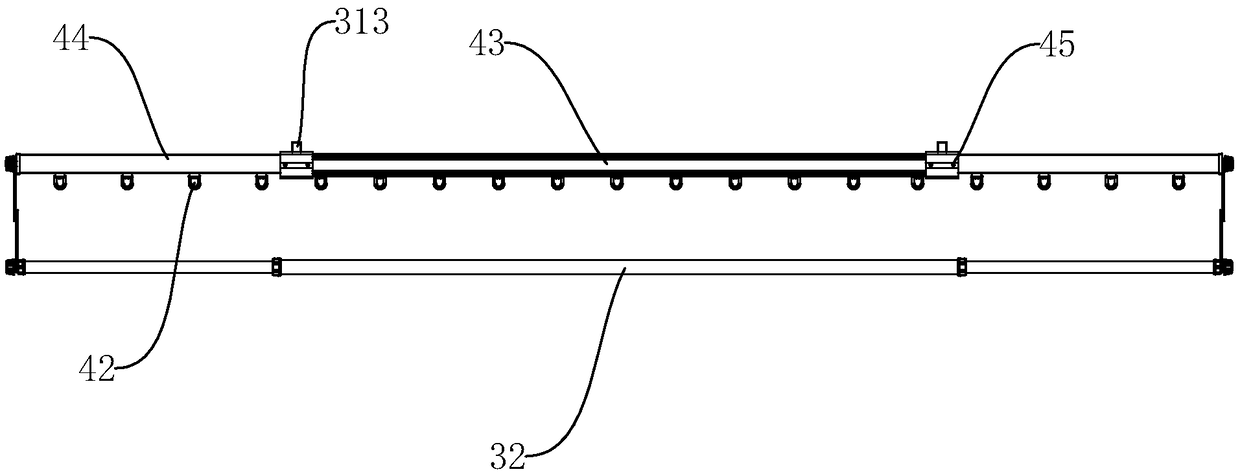
[0038] Such as Figures 1 to 9BShown is a new type of automatic drying rack, which includes a main frame 10, a folding rack 20, and a pole rack 30, and the folding rack 20 is liftably connected to the main frame 10 and the drying pole frame 30, the main frame 10 is used to control the automatic lifting of the folding frame 20, the pole rack 30 includes a pair of fixed brackets 31 and a pair of clothes rails 40, the fixed brackets 31 are detachably connected to the The clothes rail 40, the lower end of the folding rack 20 is connected to the fixed bracket 31, and each clothes rail 40 is provided with a main rod 43, a pair of slave rods 44, a receiving groove 41 and a plurality of hanging rings 42, so that T...


PUM


Abstract

The invention provides a novel automatic clothes hanger and an assembling method thereof. The clothes hanger comprises a mainframe, a folding frame, and an airing rod frame. The folding frame is connected with the mainframe and the airing rod frame in a liftable manner. The mainframe is used to control the folding frame to automatically lift. The airing rod frame comprises a pair of fixed supportsand a pair of clothesline poles. The fixed support is detachably connected with the clothesline pole. The lower end of the folding frame is connected with the fixed support. Each clothesline pole isprovided with a main rod, a pair of slave rods, a holding groove, and a plurality of suspension loops. The slave rod is connected with two sides of the main rod in an extension manner. The holding groove is arranged on the bottom surfaces of the main rod and the slave rod in a horizontal manner. The suspension loop is detachably connected with the holding groove, so as to adjust the distance between the suspension loops. Thus, the detachable suspension loops replace hanging supports, volume of the clothesline pole is greatly reduced, transportation space is saved, and transportation cost is reduced.

Description

technical field [0001] The invention relates to the technical field of clothes drying racks, in particular to a novel automatic clothes drying rack suitable for self-assembly and an assembly method thereof. Background technique [0002] With the continuous improvement of living standards, automatic drying racks are becoming more and more popular, which not only saves space, but also facilitates the drying operation of residents. The automatic clothes hanger generally has two drying rods on each side. The upper drying rod has a hanging hole, which is a clothes drying rod 40A. The lower drying rod is rotatably connected to the clothes drying rod 40A. It is mainly used for drying quilts, sheets, etc. Expand article, be airing quilt bar 32A. Most of the clothes-drying pole 40A and quilt-drying pole 32A on the market are circular tube structures, and both sides of the clothes-drying pole 40A and the quilt-drying pole 32A are equipped with telescopic secondary poles 44A, which ca...

Claims


Application Information

Patent Timeline
IPC IPC(8): D06F57/12
CPCD06F57/125
Inventor 沈文博毛克勇
Owner 宁波斯洛曼智能科技有限公司
Learn More