Large-diameter ultra-deep high-pressure jet grouting construction method

A construction method, a technology of high-pressure injection, which is applied in the direction of basic structure engineering, construction, sheet pile walls, etc., can solve the problems of poor mud discharge, large suction port, blockage, etc., and achieve the effect of ensuring quality and little impact

Inactive Publication Date: 2018-11-30
上海勇创环境岩土工程有限公司 +1
View PDF6 Cites 2 Cited by
  • Summary
  • Abstract
  • Description
  • Claims
  • Application Information

AI Technical Summary

Problems solved by technology

[0004] However, through a large number of actual conditions of on-site construction, it is found that the mud discharge suction port is easily blocked by larger soil blocks, and sometimes due to the high density of the mud, it is easy to cause the mud suction port to be blocked, resulting in poor mud discharge, which affects the construction quality and construction progress.

Method used


Image

  • Large-diameter ultra-deep high-pressure jet grouting construction method
  • Large-diameter ultra-deep high-pressure jet grouting construction method
  • Large-diameter ultra-deep high-pressure jet grouting construction method

Examples


Embodiment 1

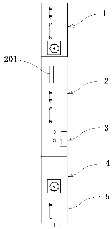
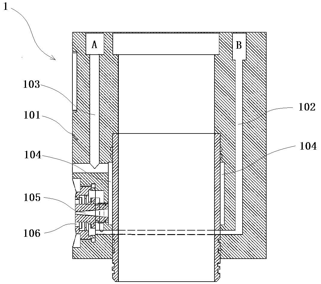
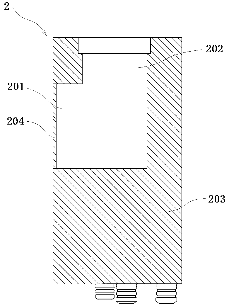
[0032] Embodiment 1: as Figure 1-9 As shown, this embodiment specifically relates to a large-diameter ultra-deep high-pressure jet grouting construction method. The construction method mainly uses the water-cutting section 1 provided at the lower end of the drilling tool 9 to water-cut the soil and utilize the slurry-returning section 2 Carry out vacuum pumping for the mud, and at the same time, use the cement slurry nozzle 403 installed horizontally on the spraying section 4 to rotate and spray the cement slurry to the periphery of the drilling tool 9 to form a rotary spraying pile body 16, which can effectively control the pressure in the ground while achieving efficient mud discharge , so as to ensure the quality of the shotcrete pile.

[0033] Such as figure 1 , 2 As shown, the water cutting section 1 includes a cylindrical water cutting section body 101, at least one cutting nozzle 105 is horizontally arranged on the outer wall surface of the water cutting section body...

Embodiment 2

[0046] Embodiment 2: as Figure 10 , 11 , 13, the difference between this embodiment and embodiment 1 is that in this embodiment, the cutting nozzle 105 is arranged inclined downwards, while the cement slurry nozzle 403 is arranged inclined upward, the two are on the same vertical line, and the two spray The emerging cutting water 15 and cement slurry 13 meet on the injection surface 18, and by adjusting the inclined setting angles of the cutting nozzle 105 and the cement slurry nozzle 403 respectively, the position of the injection surface 18 at the intersection can be controlled, that is, they meet at the set diameter position , so that a jet grouting pile body 16 with a designed diameter is formed around the drilling tool 9 .

[0047] In practical application, according to the design diameter of the jet grouting pile body 16 that needs to be applied, adjust the distance between the cutting nozzle 105 and the cement slurry nozzle 403 on the drilling tool 9 and the respectiv...

Embodiment 3

[0050] Example 3, such as Figure 12 As shown, the difference between this embodiment and Embodiment 2 is that in this embodiment, a horizontally arranged cutting nozzle 105 is added to the water cutting section 1, and the horizontally arranged cutting nozzle 105 can improve the soil around the drilling tool 9. For powerful cutting, while the diameter of the jet grouting pile body can be effectively controlled according to the construction requirements, it can also ensure that the diameter of the jet grouting pile body 16 is sufficiently large.


PUM


Abstract

The invention discloses a large-diameter ultra-deep high-pressure jet grouting construction method. The construction method is characterized by comprising the following steps: adopting a hole guidingdrilling machine to guide a hole at a point to be grouted; after hole formation, lowering a drilling tool of a rotary jet machine to the bottom of the hole, wherein the lower end of the drilling toolis provided with a water cutting section and a spraying section, and the water cutting section is located on the upper portion of the spraying section; operating the rotary jet machine, lifting the drilling tool by rotating and enabling the water cutting section to spray high pressure water flow to the outside to cut a soil body surrounding the drilling tool into slurry, and the spraying section sprays cement slurry to the outside to form a rotary jet grouting pile around the drilling tool. The method has the advantages that the water cutting section is arranged to dilute the surrounding slurry, a reversing section is synchronously arranged, and a special slurry discharge pipe is utilized to conduct centralized slurry discharge. While slurry discharge is conducted efficiently, the internalpressure is effectively controlled, the grouting and pile formation quality is ensured, and the effect on the surrounding environment is small.

Description

technical field [0001] The invention belongs to the technical field of foundation construction, and in particular relates to a large-diameter ultra-deep high-pressure jet grouting construction method. Background technique [0002] In the construction of traditional high-pressure grouting method, the mud is naturally discharged on the ground through the gap around the drill pipe. However, it is very difficult to discharge mud at deep depths, because the pressure in the ground around the ultra-deep drill pipe and the high-pressure injection port increases, which often leads to a decrease in injection efficiency, so the reinforcement effect and reliability are reduced. In addition, during the construction process, the internal pressure increases, which will cause the surrounding surface to bulge. [0003] The MJS construction method (Metro Jet System) is also known as the all-round high-pressure jet grouting method. On the basis of the traditional high-pressure jet grouting pr...

Claims


Application Information

Patent Timeline
IPC IPC(8): E02D15/04E02D5/46
CPCE02D5/46E02D15/04E02D2250/003E02D2250/0053
Inventor 陈军郭星宇黄朝昱宣霖康朱进成王蓉陈相茂冯凯
Owner 上海勇创环境岩土工程有限公司
Why Eureka
Try Eureka