A laser remote sensing detection system and method

A detection system and laser technology, applied in the field of laser detection, can solve the problems of increased cost and volume, inability to obtain distance, complex overall structure of a remote sensing detection device, etc., and achieve the effect of simplifying the structure

Inactive Publication Date: 2018-11-30
HESAI TECH CO LTD
View PDF6 Cites 1 Cited by
  • Summary
  • Abstract
  • Description
  • Claims
  • Application Information

AI Technical Summary

Problems solved by technology

[0003] In the application of laser remote sensing to detect gas concentration (hereinafter referred to as laser gas remote measurement), the result of general remote measurement is only the concentration of gas, and the distance of remote measurement cannot be obtained.
In order to be able to realize both the remote measurement of the gas concentration and the remote measurement of the distance, in the prior art, a laser distance measuring device is generally installed outside the laser gas telemetry device to realize the distance measurement. Obviously, by installing a laser distance measurement Although the device can realize the remote measurement of the distance, the overall structure of the remote sensing detection device is more complicated due to the addition of additional equipment, and the cost and volume are greatly increased.

Method used


Image

  • A laser remote sensing detection system and method
  • A laser remote sensing detection system and method
  • A laser remote sensing detection system and method

Examples


Embodiment 1

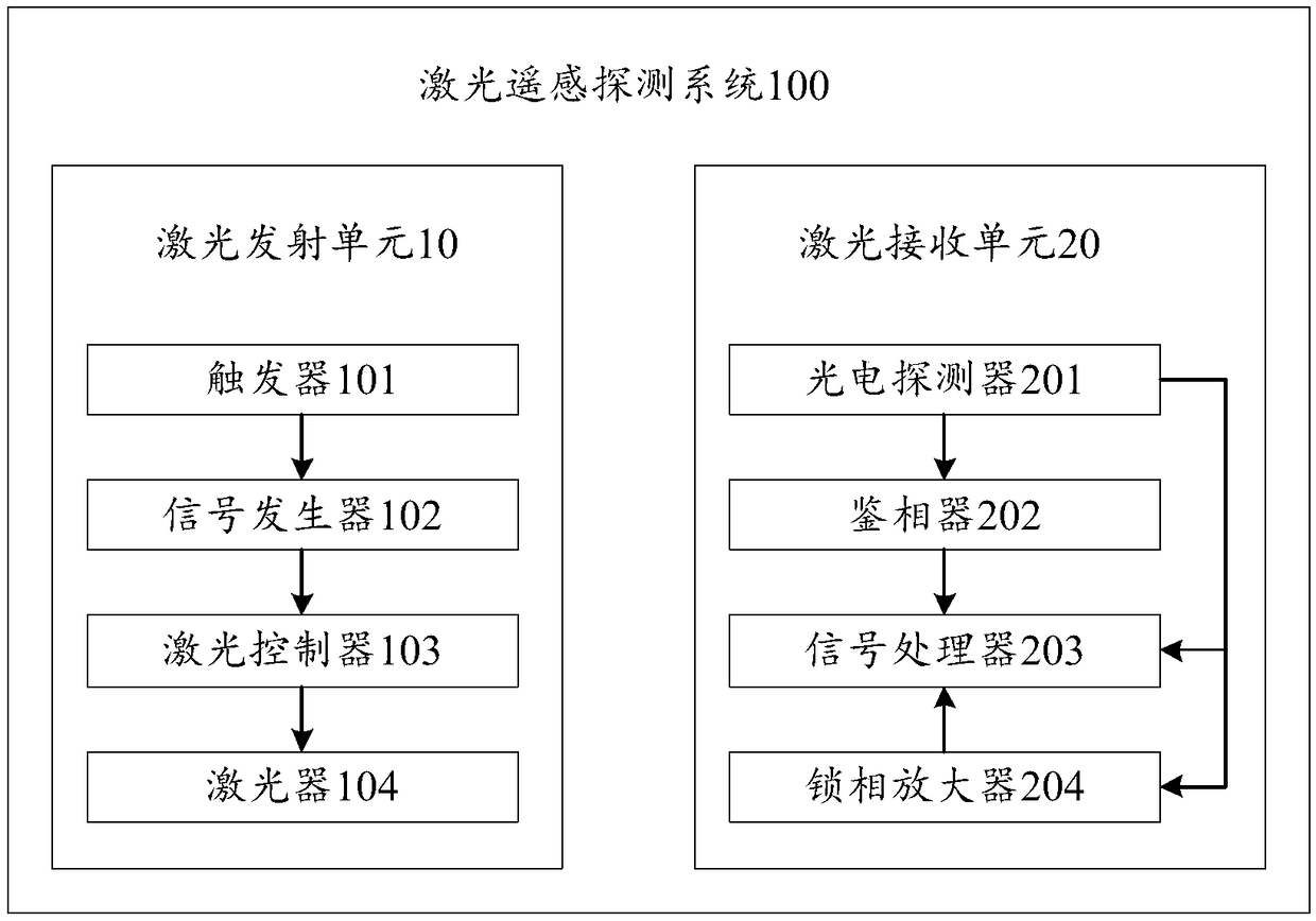
[0041] Please refer to figure 1 , which is a schematic structural diagram of a laser remote sensing detection system provided by an embodiment of the present invention. The laser remote sensing detection system 100 can realize remote measurement of distance and remote measurement of gas concentration by means of time-sharing measurement.

[0042] Such as figure 1 As shown, the laser remote sensing detection system 100 includes a laser emitting unit 10 and a laser receiving unit 20, the laser emitting unit 10 is used to emit detection laser light, the laser receiving unit 20 is used to receive the reflected laser reflection signal, and perform a Process and output the detection results.

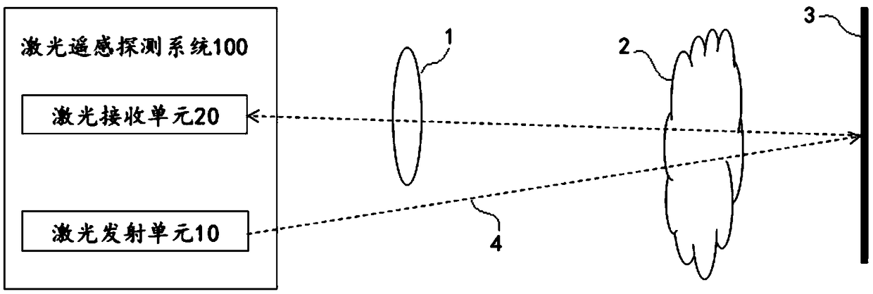
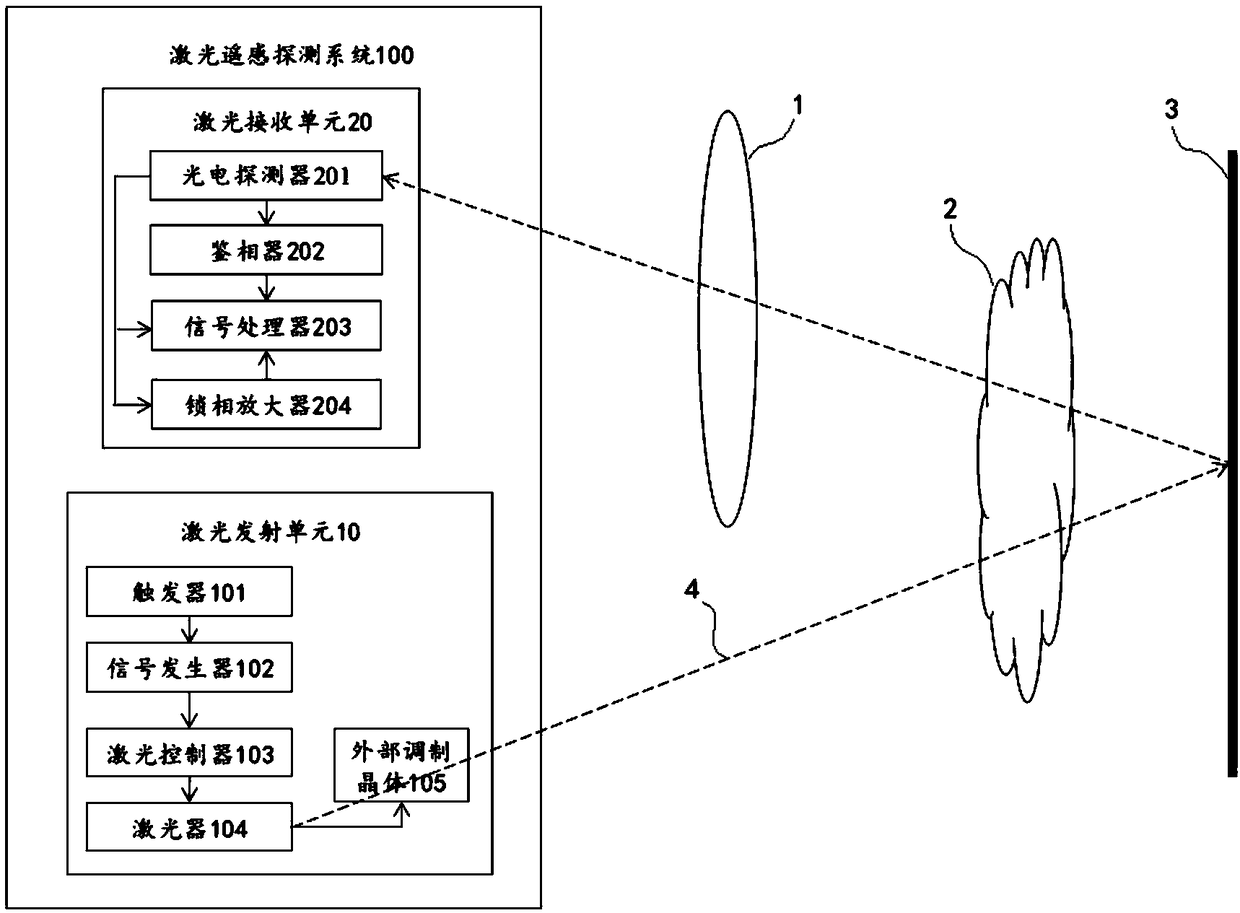
[0043] Please refer to figure 2 , which shows an applicable optical path diagram of the laser remote sensing detection system provided by the embodiment of the present invention. Such as figure 2 As shown, the detection laser 4 emitted by the laser emitting unit 10 penetrates into the me...

Embodiment 2

[0079] This embodiment provides a laser remote sensing detection method, which can use the laser remote sensing detection system 100 in Embodiment 1. Specifically, the laser remote sensing detection method includes the following steps:

[0080] S1, the trigger alternately sends the first detection state trigger signal and the second detection state trigger signal to the signal generator;

[0081] S2, the signal generator receives the first detection state trigger signal or the second detection state trigger signal, generates the first modulation signal or the second modulation signal according to the first detection state trigger signal or the second detection state trigger signal, and converts the first modulation signal to The signal or the second modulation signal is injected into the laser controller;

[0082]S3. The laser controller modulates the output of the laser according to the first modulation signal or the second modulation signal.

[0083] Of course, it can be u...


PUM


Abstract

A laser remote sensing detection system and method are disclosed. First and second detection state triggering signals can be sent alternatively to a signal generator through a trigger so that the system is alternate between a first detection state (a distance measuring state) and a second detection state (a gas concentration measuring state), thus achieving two functions which are distance measuring and gas concentration measuring through a time-shared measurement manner. The distance measuring function is achieved on the basis of not changing the optical frame of a laser gas remote sensing device, thus simplifying the structure and reducing the cost and size of the detection system.

Description

technical field [0001] The invention relates to the technical field of laser detection, in particular to a laser remote sensing detection system and method. Background technique [0002] At present, laser remote sensing detection technology has been widely used in the detection of harmful gas concentration, especially the gas that is difficult to directly measure the concentration of methane. Laser remote sensing gas concentration detection has the following advantages: high measurement accuracy; faster measurement speed and quick response than other measurement methods; on-site measurement can be realized; low requirements for the surrounding environment, and the harsh gas environment will not seriously affect the measurement accuracy ; This technology can be applied in the concentration detection of dozens of common gases such as methane and hydrogen sulfide. [0003] In the application of laser remote sensing to detect gas concentration (hereinafter referred to as laser ...

Claims


Application Information

Patent Timeline
Patent Type & Authority Applications(China)
IPC IPC(8): G01N21/31
CPCG01N21/31
Inventor 陶俊向少卿李一帆
Owner HESAI TECH CO LTD
Why Eureka
Try Eureka