
A kind of preparation method of flow rate sensor

A flow velocity sensor, square technology, applied in fluid velocity measurement, instrument, velocity/acceleration/shock measurement, etc., can solve problems such as unfavorable arrangement, complex structure of gas velocity sensor, etc., achieve easy micro-patterning and batch production, preparation method simple effect

Active Publication Date: 2020-08-14
BEIHANG UNIV
View PDF1 Cites 0 Cited by
  • Summary
  • Abstract
  • Description
  • Claims
  • Application Information

AI Technical Summary

Problems solved by technology

[0005] The purpose of the present invention is to provide a flow velocity sensor and its preparation method, which can solve the technical problems that the existing gas flow velocity sensor has a complex structure and is not conducive to being arranged on the surface of the flexible airfoil of a micro aircraft

Method used


Image

  • A kind of preparation method of flow rate sensor
  • A kind of preparation method of flow rate sensor
  • A kind of preparation method of flow rate sensor

Examples


Embodiment Construction

[0039] The technical solutions in the embodiments of the present invention will be clearly and completely described below in conjunction with the accompanying drawings in the embodiments of the present invention. Obviously, the described embodiments are only a part of the embodiments of the present invention, rather than all the embodiments. Based on the embodiments of the present invention, all other embodiments obtained by those of ordinary skill in the art without creative work shall fall within the protection scope of the present invention.

[0040] The purpose of the present invention is to provide a flow rate sensor and a preparation method thereof, which can solve the technical problem that the existing gas flow rate sensor has a complicated structure and is not conducive to being arranged on the surface of a flexible airfoil of a micro aircraft.

[0041] In order to make the above objectives, features and advantages of the present invention more obvious and understandable, t...


PUM


Abstract

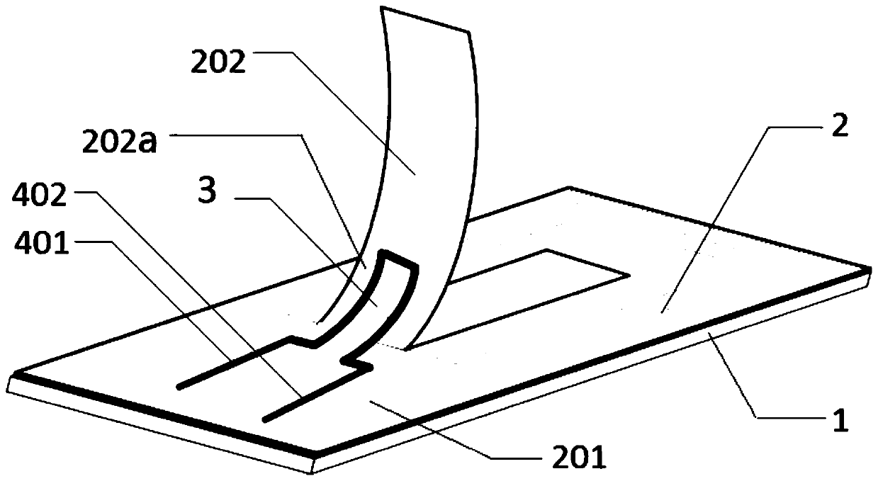
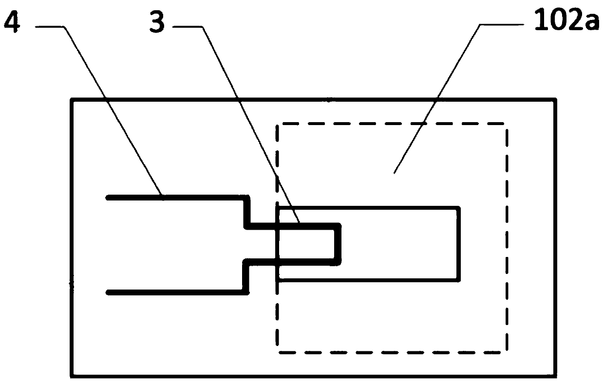
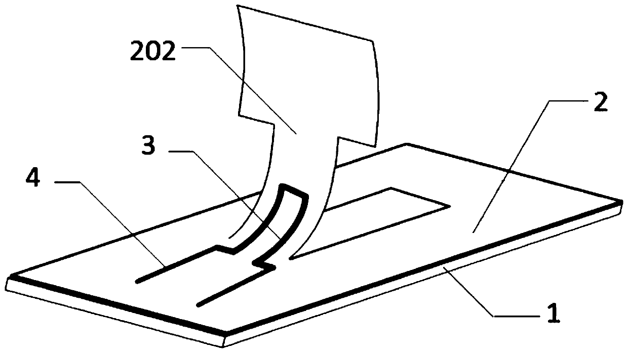
The invention discloses a flowing speed sensor and a fabrication method thereof. The flowing speed sensor comprises a dual-layer polyimide film substrate, a graphene / polyimide piezoresistance unit anda signal lead. By arranging a simulated hair structure and the graphene / polyimide piezoresistance unit on a surface of the dual-layer polyimide film substrate, the flowing speed can be further measured by measuring stress change of the piezoresistance unit caused by bending of the simulated hair structure under an effect of an external fluid. The flowing speed sensor is simple in structure, and mass production is easy; with the design of employing simulated hair to sensor the flowing speed of the external fluid, the flowing speed sensor has the advantages of structural sensitivity and high measurement accuracy; and moreover, the flowing speed sensor employs a polyimide film as a flexible substrate, and the flowing speed sensor is more conveniently arranged on an arc wing surface and otherprobable curved surfaces.

Description

Technical field [0001] The invention relates to the technical field of flow rate measurement, in particular to a flow rate sensor and a preparation method thereof. Background technique [0002] The flow sensor is an indispensable means for underwater autonomous robots and self-stabilizing micro-aircraft to sense changes in the external flow field. Especially for small and light micro-aircraft, real-time perception of the flow field on the wing surface in a complex environment is the key to improving its wind resistance and realizing active control of the flight process. [0003] Traditional flow velocity measurement methods, such as hot wire anemometers, turbine flow meters, acoustic Doppler frequency shift velocity measurement and particle image tracing, cannot meet the application requirements of the above-mentioned micro-aircraft due to their large size, low sensitivity, and complex structure. As a new type of micro-sensor, the hair sensor is designed to imitate the biological ...

Claims


Application Information

Patent Timeline
Patent Type & Authority Patents(China)
IPC IPC(8): G01P5/08
CPCG01P5/08
Inventor 蒋永刚沈大卫张德远刘梦洋
Owner BEIHANG UNIV
Learn More