Distributed distribution automation station terminal DTU based on wireless transmission technology

A wireless transmission, automation station technology, applied in information technology support systems, electrical components, circuit devices, etc., can solve the problems of difficult maintenance, difficult to replace lines, complicated DTU wiring, etc., to facilitate maintenance and maintenance, and improve construction. The effect of installation efficiency and reduction of installation difficulty

Pending Publication Date: 2018-11-30
NANJING XINLIAN ENERGY TECH
View PDF4 Cites 1 Cited by
  • Summary
  • Abstract
  • Description
  • Claims
  • Application Information

AI Technical Summary

Problems solved by technology

[0003] The present invention proposes a distributed power distribution automation station terminal DTU based on wireless transmission technology. WIFI transmission, a distributed distribution automation station terminal DTU based on wireless transmission technology that effectively saves construction time and construction costs

Method used


Image

  • Distributed distribution automation station terminal DTU based on wireless transmission technology
  • Distributed distribution automation station terminal DTU based on wireless transmission technology
  • Distributed distribution automation station terminal DTU based on wireless transmission technology

Examples


Embodiment approach

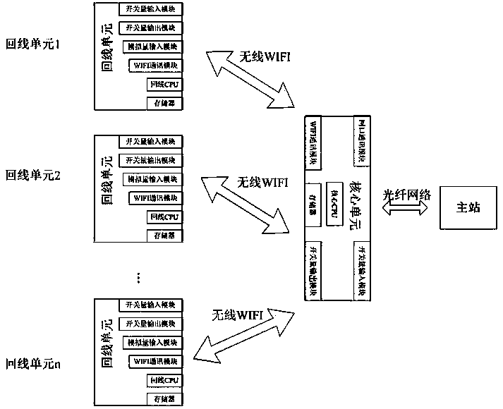
[0014] The implementation method includes the following steps:

[0015] (1) The core unit is connected to the master station;

[0016] (2) The loop unit is connected to the core unit;

[0017] (3) The core unit, loop unit acquisition control and data transmission and sharing with the master station.

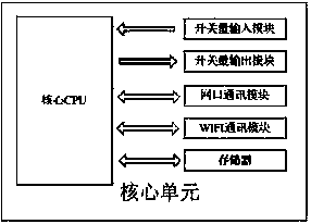
[0018] The steps (1) connecting the core unit to the master station includes: 1) powering on the core unit to complete the initialization of each module; 2) setting the master station address according to the master station information, and connecting the master station through the optical fiber network; 3) the master station according to DTU For the user information of the device, establish a user profile in the master station.

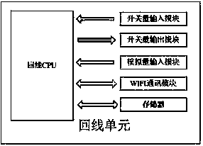
[0019] The step (2) connecting the loop unit to the core unit includes: 1) power on the loop unit to complete the initialization of each module; 2) wait for the core unit to power on, and set the loop unit parameters according to the core unit WIFI address, Mak...

Embodiment 1

[0028] When implemented, it specifically includes the following steps: A) the core unit is connected to the main station; B) the loop unit is connected to the core unit; C) the core unit, loop unit acquisition control, and data transmission and sharing with the main station;

[0029] A) The core unit is connected to the master station, after the core unit is powered on

[0030] (1) The system is powered on to complete the initialization of each module;

[0031] (2) Set the master station address according to the master station information, and connect to the master station through the optical fiber network;

[0032] (3) The master station establishes user files in the master station according to the user information of the DTU equipment;

[0033] B) The loop unit is connected to the core unit, and the loop unit is powered on first:

[0034] (1) The system is powered on to complete the initialization of each module;

[0035] (2) After waiting for the core unit to be powered on, according t...


PUM


Abstract

The invention is a distributed distribution automation station terminal DTU based on wireless transmission technology. The terminal comprises a core unit and a plurality of loop units, wherein the core unit communicates with a master station through an optical network, and each of the loop units is managed through a WIFI network; the core unit receives a command from the master station and forwards the command to the loop units for control, the loop units perform corresponding operations and control according to the situation of collection and calculation, and simultaneously report to the coreunit, and the core unit forwards the information to the distribution master station. The distributed distribution automation station terminal has the advantages of: 1) facilitating repair and maintenance and improving the efficiency for maintenance and repair since a large amount of physical cables are not needed for laying during a site operation by applying the wireless network and loop units for communication through the core unit, resulting in no need to check every cable when the equipment fails; and 2) effectively reducing the install difficulty of site operations, improving the construction and installation efficiency, and obviously reducing the cost.

Description

Technical field [0001] The invention is a distributed distribution automation station terminal DTU based on wireless transmission technology, and belongs to the technical field of distribution automation station terminals. Background technique [0002] Switching stations, ring network cabinets, and substations have been widely used in distribution automation station terminals to realize the collection, control, and fault detection of multiple lines. In the existing power distribution automation station terminal, the core unit and the return line unit need to be physically wired to collect the control communication signal volume during the installation and construction. The farther the relative physical location of the core unit and the return line unit, the more complicated the wiring. The more return lines, the more wiring is required, and the wiring process is complicated. It is difficult to overhaul when there is a problem, and it is difficult to replace the line again, which...

Claims


Application Information

Patent Timeline
Patent Type & Authority Applications(China)
IPC IPC(8): H02J13/00
CPCH02J13/0075Y04S40/124Y04S40/126Y02E60/00
Inventor 张长玉夏令王爱民翟亮李巧媛
Owner NANJING XINLIAN ENERGY TECH
Why Eureka
Try Eureka