Design method of low-frequency multi-sinusoidal signals based on linearized model identification of power system
A sinusoidal signal, power system technology, applied in character and pattern recognition, calculation, computer parts and other directions, can solve the problem of reducing the signal-to-noise ratio of the output response signal, affecting the identification accuracy of the power system multi-input multi-output linearization model, and the input signal The energy is not concentrated enough to achieve the effect of small disturbance
- Summary
- Abstract
- Description
- Claims
- Application Information
AI Technical Summary
Problems solved by technology
Method used
Image
Examples
Embodiment
[0033] A low-frequency multi-sine signal design method for multi-input multi-output linearization model identification proposed by the present invention, such as Figure 5 shown, including the following steps:
[0034] initial startup
[0035] (1) Determine the time-domain length of the low-frequency multi-sine signal as N, and the expected crest factor as C r,set , the corresponding Fourier coefficient record variable is FS, the amplitude record variable is Mag, and the phase record variable is Pha, and the initial FS, Mag, and Pha are all zero vectors with length N.
[0036] (2) Determine the harmonic component frequency ω of the low-frequency multi-sine signal k and the frequency domain amplitude a k , where k=0,1,…,N k -1,N k≤N / 2, then the amplitude a k According to the harmonic component frequency ω k The position corresponding to the amplitude record variable Mag is filled in the amplitude record variable Mag, so as to obtain the amplitude-frequency characteristic...
Embodiment 2
[0051] An embodiment of the method of the present invention is described below.
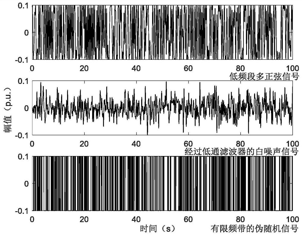
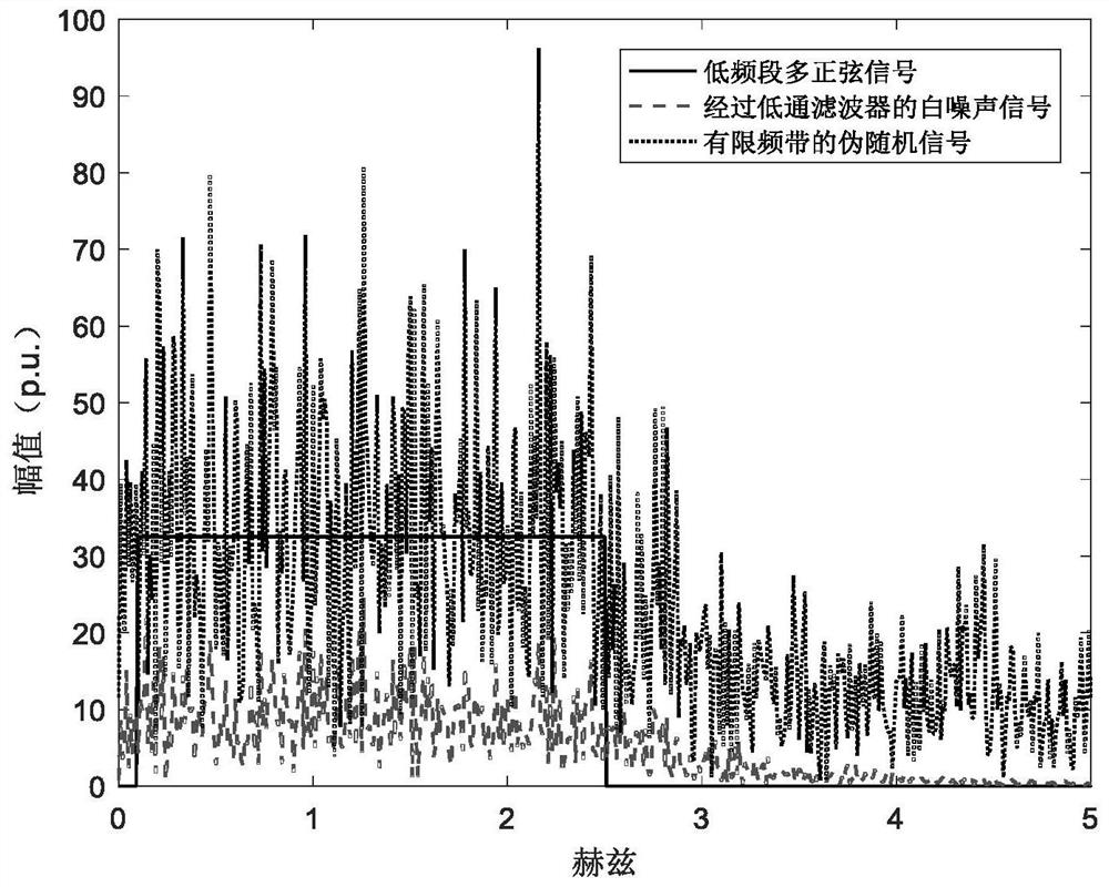
[0052] The method of the invention is used to generate a low-frequency multi-sine signal whose frequency domain energy is concentrated at 0.1-2.5 Hz, and a traditional method is used to generate a white noise signal through a low-pass filter and a pseudo-random signal with a limited frequency band. Among them, the white noise signal through the low-pass filter is obtained by filtering the white noise signal with a 5th-order Butterworth filter with a cutoff frequency of 2.5 Hz, and the pseudo-random signal with a limited frequency band is the white noise signal that will pass through the low-pass filter The amplitude of the signal is obtained by reassigning the sign to ±1p.u. The three low-frequency input signal lengths are all 100s, and the sampling rate is 100Hz, and the amplitude of the signal in the time domain is limited to ±0.1p.u.
[0053] figure 1 are the time-domain waveforms of three l...
PUM
 Abstract
Description
Claims
Application Information
 - R&D
- Intellectual Property
- Life Sciences
- Materials
- Tech Scout
- Unparalleled Data Quality
- Higher Quality Content
- 60% Fewer Hallucinations
Browse by: Latest US Patents, China's latest patents, Technical Efficacy Thesaurus, Application Domain, Technology Topic, Popular Technical Reports.
© 2025 PatSnap. All rights reserved.Legal|Privacy policy|Modern Slavery Act Transparency Statement|Sitemap|About US| Contact US: help@patsnap.com


