High-speed railway broadband communication technology

A high-speed railway and broadband technology, applied in railway signal, railway car body parts, railway signal and safety, etc., can solve the problems of scarcity of mobile communication frequency band spectrum resources, uneconomical data transmission, large vehicle-mounted antenna, etc., and achieve easy universal use The effect of standardization and standardization, simple signal processing method, and low construction cost

Inactive Publication Date: 2018-12-04
西安绿行户外运动有限公司
View PDF0 Cites 0 Cited by
  • Summary
  • Abstract
  • Description
  • Claims
  • Application Information

AI Technical Summary

Problems solved by technology

[0004] First of all, this method uses mobile communication coverage technology for broadband transmission, and the frequency and bandwidth used are limited to a certain extent. Because the spectrum resources in the mobile communication frequency band are scarce and expensive, it is very difficult to use a large frequency band for data transmission. Uneconomical
[0005] Secondly, to realize the business transmission between trains and roads by building Tabu base stations along the railway line, it is necessary to coordinate resources such as land and electricity along the line. Tunnels and stations still need to coordinate internal resources of the railway department, and there are many uncontrollable factors; due to signal relay Using the mobile communication frequency band, the vehicle-mounted antenna is bulky and difficult to conform to the vehicle body, resulting in certain driving safety hazards
[0006] In addition, due to the need for a large number of other guarantees that are not required by the communication system itself, the construction of a complete communication system requires huge operating costs and high risk of profitability
[0007] Most importantly, since the construction of this system involves complex environmental resources, it is difficult to standardize, generalize and promote the system

Method used


Image

  • High-speed railway broadband communication technology
  • High-speed railway broadband communication technology
  • High-speed railway broadband communication technology

Examples


Embodiment Construction

[0043] Below in conjunction with accompanying drawing and embodiment the present invention will be further described:

[0044] The so-called railway building boundary in the present invention refers to a limit cross-sectional profile perpendicular to the center line of the railway. Except for electric wires and others), other equipment or buildings shall not be invaded. The specific size definition of the railway building gauge is defined by the national standard of the People's Republic of China "Standard Gauge Railway Building Gauge" (GB146. 2-2006) etc. are given.

[0045] The train referred to in the following embodiments of the present invention is one of the specific implementations of the carrier referred to in the present invention.

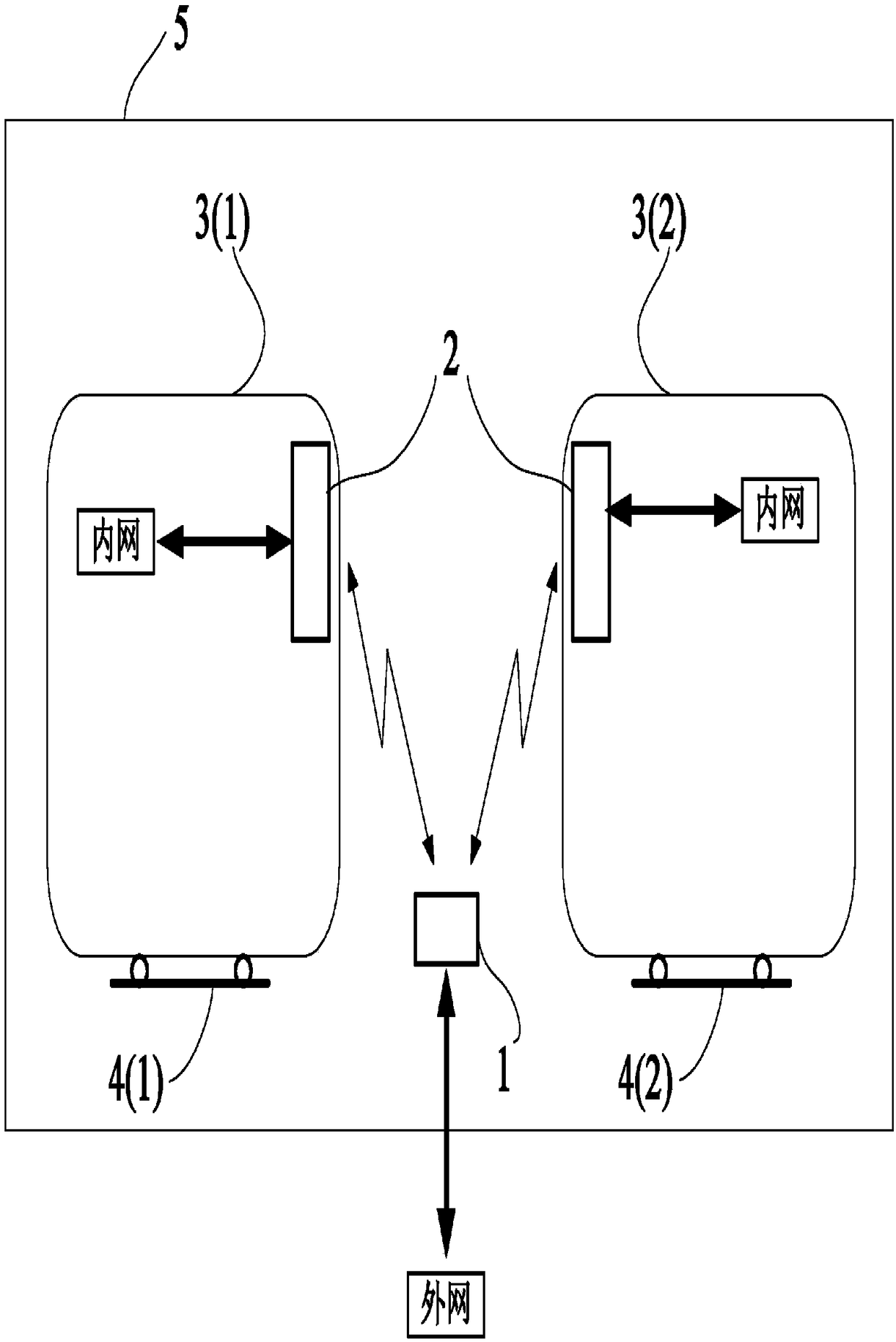
[0046] see figure 1 , is a functional block diagram of the broadband communication technology of the high-speed railway in the present invention, mainly including a rail-based relay device 1 arranged along the high-speed railway track ...


PUM


Abstract

In the invention, a high-speed railway broadband communication technology is designed for realizing signal relay between an internal communication network of a motion carrier and an external communication network of the carrier on a high-speed railway. The technology is characterized in that a network comprises a plurality of rail base relay devices and at least one vehicle-mounted relay device, wherein the plurality of rail base relay devices are arranged along high-speed railway rails and are mounted within a rail construction limit, and the rail base relay devices are used for realizing signal relay between the external communication network and the vehicle-mounted relay device; each rail base relay device forms a coverage space; the at least one vehicle-mounted relay device is fixed onthe carrier, and signal relay can be realized between rail base relay devices corresponding to current coverage spaces and the internal communication network of the carrier; a frequency range of thesignal is limited in one or more sub-frequency ranges from 4 to 42 GHz. The invention mainly relates to the high-speed railway broadband communication technology, in particular to a solution for realizing access and return of broadband signals on a high-speed train.

Description

technical field [0001] The invention mainly relates to the broadband communication technology of the high-speed railway, especially the solution for realizing the access and return of the broadband signal on the high-speed train. Background technique [0002] In recent years, with the rapid development of high-speed railway construction and information construction, it is necessary to build a stable broadband communication system between high-speed trains and roads to meet the needs of mobile phones, Internet access, live news broadcasts, and integrated information service systems. need. [0003] The existing communication method of access and backhaul is to use TD-LTE technology in the mobile communication frequency band, and adopt the method of building a tower base station along the railway line to realize the service transmission between the train and the road. But this technology has the following disadvantages: [0004] First of all, this method uses mobile communica...

Claims


Application Information

Patent Timeline
Patent Type & Authority Applications(China)
IPC IPC(8): H04B7/026H04B7/06H04B7/08H04B7/155B61L15/00
CPCH04B7/026B61L15/00B61L2205/00H04B7/0697H04B7/08H04B7/155
Inventor 刘坤
Owner 西安绿行户外运动有限公司
Why Eureka
Try Eureka