Electrostatic powder spraying equipment for electromechanical

A technology of electrostatic powder and spraying equipment, which is applied in the direction of spraying devices and liquid spraying devices, which can solve the problems of affecting the uniformity of spraying, lack of cleaning equipment, and easy loosening, so as to improve the fixing fastness, improve the quality of spraying, reduce particle size effect

Active Publication Date: 2020-09-25
HENAN INST OF SCI & TECH
View PDF6 Cites 0 Cited by
  • Summary
  • Abstract
  • Description
  • Claims
  • Application Information

AI Technical Summary

Problems solved by technology

[0002] In the electromechanical industry, anti-electricity parts are often used to maintain the operation of electromechanical equipment. During the manufacturing process of parts, a layer of powder is usually sprayed on the surface of the parts to make the parts insulated, so as to ensure the parts in the electromechanical The equipment can work normally; the electrostatic powder spraying equipment in the prior art has a complicated structure, and the powder cannot be processed during use, so that the particle size of the powder is different, which seriously affects the uniformity of the spraying, and, for different parts in When fixed, the fixing effect is poor, and it is prone to loosening, resulting in unsatisfactory spraying quality. At the same time, the spraying equipment in the prior art lacks cleaning equipment after the spraying is completed, so that a large amount of powder remains on the workbench. Therefore, it is necessary to design a It is necessary to use electrostatic powder coating equipment for electromechanical

Method used


Image

  • Electrostatic powder spraying equipment for electromechanical
  • Electrostatic powder spraying equipment for electromechanical
  • Electrostatic powder spraying equipment for electromechanical

Examples


Embodiment Construction

[0031] The following will clearly and completely describe the technical solutions in the embodiments of the present invention with reference to the accompanying drawings in the embodiments of the present invention. Obviously, the described embodiments are only some, not all, embodiments of the present invention. Based on the embodiments of the present invention, all other embodiments obtained by persons of ordinary skill in the art without making creative efforts belong to the protection scope of the present invention.

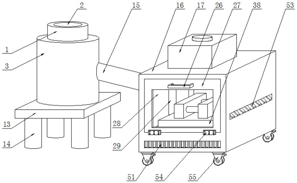
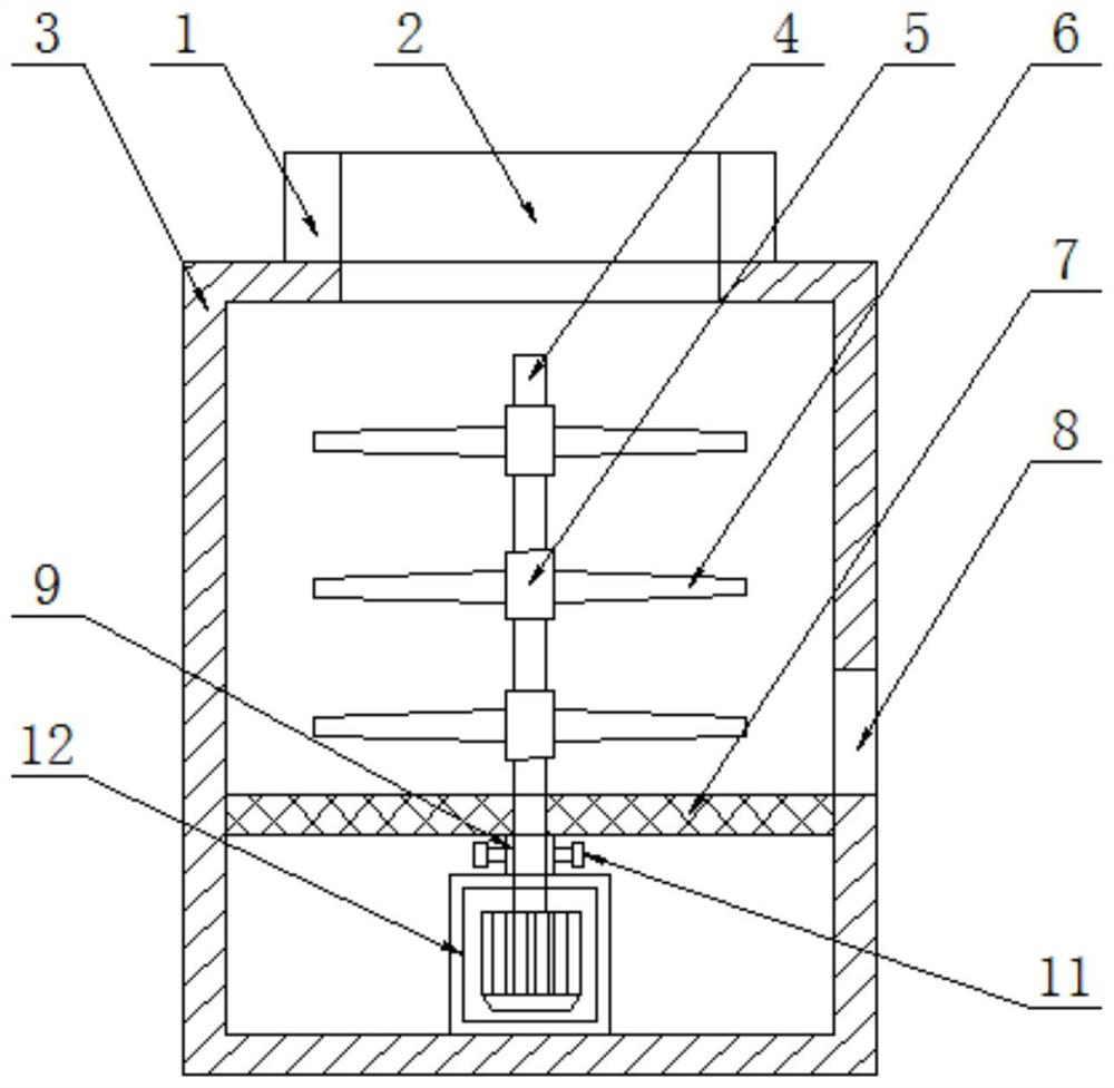
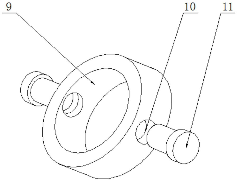
[0032] see Figure 1-8, the present invention provides a technical solution: an electromechanical electrostatic powder spraying equipment, including a feed table 1, a feed port 2, a stirring tank 3, a stirring shaft 4, a shaft sleeve 5, a stirring frame 6, a material partition 7, Discharge port 8, fastening sleeve 9, fastening hole 10, lock nut 11, stirring motor 12, base 13, support frame 14, feeding pipe 15, chassis 16, cleaning box 17, water inlet 18, water...


PUM


Abstract

The invention discloses an electrostatic power spraying equipment for machines and electricity. The electrostatic power spraying equipment for machines and electricity comprises a feeding table, a feeding hole, a stirring tank, a stirring shaft, a shaft sleeve, a stirring frame, a material separation plate, a discharging hole, a fastening sleeve, a fastening hole, a locking nut, a stirring motor,a base, a support frame, a material conveying pipe, a machine case, a cleaning box, a water inlet table, a water inlet, a water storage box, a water box baffle plate, a water conveying pipe, a clean water pump, a water draining pipe, a clean spray head, a handle, a box cover, an observing window, a spraying box, a material conveying hole, a first feeding pipe, a delivery pump, a T-shaped pipe, a first power spray head, a second feeding pipe, a second power spray head, an electrostatic generator, a workbench, a rotary knob, a movable clamping plate, a fastening threaded rod, a fixed clamping plate, a hinge and moving wheels, wherein the stirring tank is arranged on the top of the base through a bolt. The spraying equipment is convenient to install, can avoid the shaft runout generated in astirring shaft, has a wide spraying range and a cleaning function, and is reliable in clamping and fixation. The convenience of the electrostatic power spraying equipment for machines and electricityin use is greatly improved.

Description

technical field [0001] The invention relates to the field of electromechanical technology, in particular to an electrostatic powder coating equipment for electromechanical. Background technique [0002] In the electromechanical industry, anti-electricity parts are often used to maintain the operation of electromechanical equipment. During the manufacturing process of parts, a layer of powder is usually sprayed on the surface of the parts to make the parts insulated, so as to ensure the parts in the electromechanical The equipment can work normally; the electrostatic powder spraying equipment in the prior art has a complicated structure, and the powder cannot be processed during use, so that the particle size of the powder is different, which seriously affects the uniformity of the spraying, and, for different parts in When fixed, the fixing effect is poor, and it is prone to loosening, resulting in unsatisfactory spraying quality. At the same time, the spraying equipment in ...

Claims


Application Information

Patent Timeline
Patent Type & Authority Patents(China)
IPC IPC(8): B05B15/20B05B9/04B05B13/02B05B14/00
CPCB05B9/0403B05B13/02B05B14/00B05B15/20
Inventor 付广春张伟樊广晓
Owner HENAN INST OF SCI & TECH
Why Eureka
Try Eureka