Directional casting machine for nonferrous metals

A technology of directional casting and non-ferrous metals, applied in the field of castings, can solve the problems of large torsional yield stress of castings, achieve the effects of improving grain structure, ensuring behavior and improving production efficiency

Inactive Publication Date: 2018-12-07
CHENGDU SHUHONG EQUIP MFG
View PDF11 Cites 0 Cited by
  • Summary
  • Abstract
  • Description
  • Claims
  • Application Information

AI Technical Summary

Problems solved by technology

[0004] The invention overcomes the deficiencies of the prior art, provides a non-ferrous metal directional caster that can make the castings have no torsional yield stress, and solves the problem that the torsional yield stress of the castings produced by the existing casters is relatively large

Method used


Image

  • Directional casting machine for nonferrous metals
  • Directional casting machine for nonferrous metals

Examples


Embodiment 1

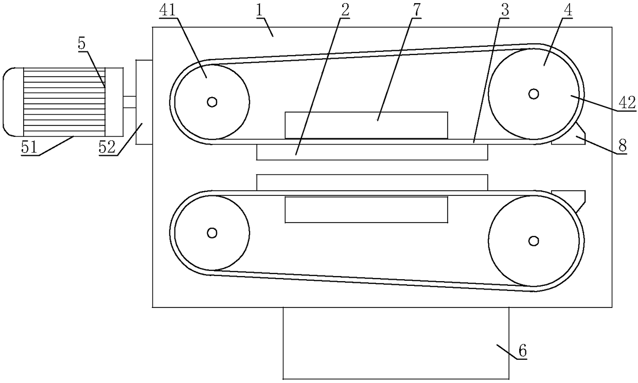
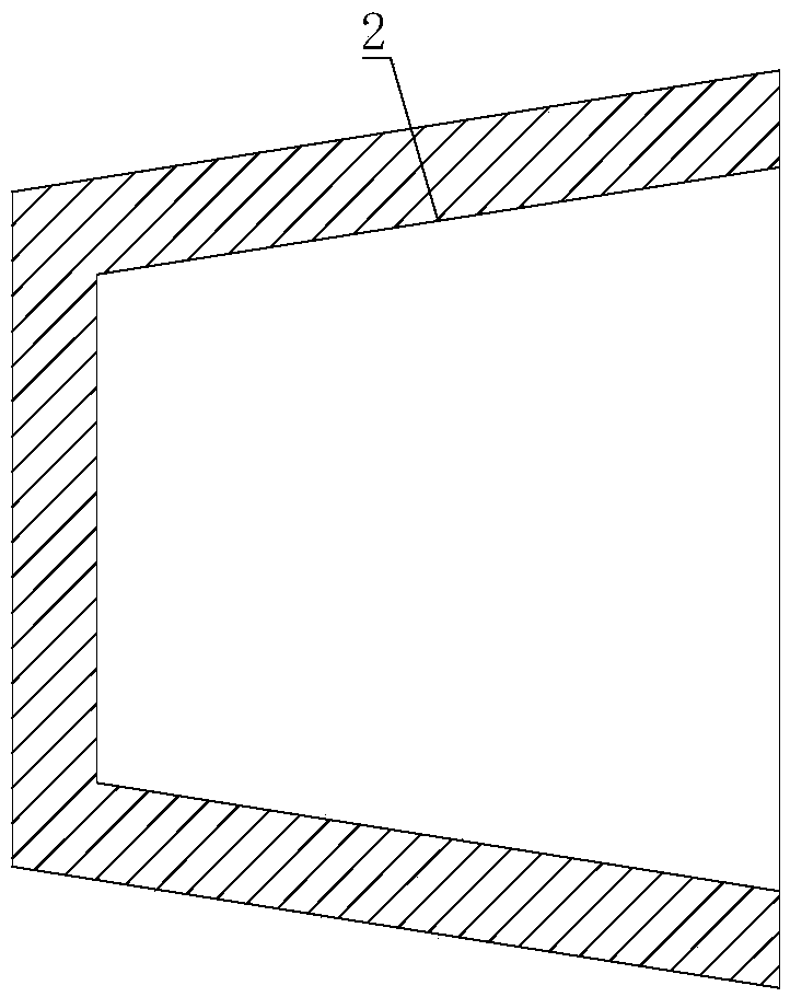
[0025] A non-ferrous metal directional caster, comprising a frame 1, a crystallizer 2 is installed on the frame 1, one side of the crystallizer 2 is open, and a steel strip 3 is assembled on one side of the crystallizer 2 opening, and the steel strip 3 is connected with the crystallizer 2 form a trapezoidal cavity, the shape of the trapezoidal cavity is a trapezoidal column, one end of the trapezoidal cavity is provided with a casting port, the other end of the trapezoidal cavity is provided with a discharge port, and the frame 1 is equipped with a steel belt 3 Continuously moving pulling mechanism 4 , a driving mechanism 5 for driving the pulling mechanism 4 is installed on the frame 1 , and the output shaft of the driving mechanism 5 is connected with the pulling mechanism 4 .

[0026] The driving mechanism 5 of the present invention drives the pulling mechanism 4 to act, and the pulling mechanism 4 can pull the steel belt 3 to move continuously, and then the casting can be c...

Embodiment 2

[0028] On the basis of Embodiment 1, the pulling mechanism 4 includes a driving wheel 41 and a driven wheel 42, the driving wheel 41 and the driven wheel 42 are installed on the frame 1 through bearings, the rotating shaft of the driving wheel 41 and the output shaft of the driving mechanism 5 Connection, the steel belt 3 is connected end to end, and the steel belt 3 is lapped on the driving wheel 41 and the driven wheel 42.

[0029] The driving mechanism 5 can drive the driving wheel 41 to rotate, then the driving wheel 41 drives the steel belt 3 and the driven wheel 42 to move, and the steel belt 3 can continuously take the casting out of the trapezoidal mold cavity. Realized the continuous production of trapezoidal castings.

Embodiment 3

[0031] On the basis of Embodiment 1 or Embodiment 2, the driving mechanism 5 includes a motor 51 , the output shaft of the motor 51 is connected with a reducer 52 , and the output shaft of the reducer 52 is connected with the pulling mechanism 4 .

[0032] After the motor 51 starts, the motor 51 drives the speed reducer 52 to act, and the speed reducer 52 drives the pulling mechanism 4 to move, so the pulling mechanism 4 can pull the steel strip 3 continuously.


PUM


Abstract

The invention relates to the field of casting machines, in particular to a directional casting machine for nonferrous metals. According to the technical scheme, the directional casting machine for thenonferrous metals comprises a rack, a crystallizer is mounted on the rack, an opening is formed in one side of the crystallizer, and a steel belt is spliced on the open side of the crystallizer; a trapezoidal die cavity is formed between the steel belt and the crystallizer, the trapezoidal die cavity is in the shape of a trapezoidal column, a pouring gate is formed in one end of the trapezoidal die cavity, and a pull mechanism for driving the steel belt to continuously move is mounted on the rack. A driving mechanism for driving the pull mechanism to act is mounted on the rack, and an outputshaft of the driving mechanism is connected with the pull mechanism. According to the directional casting machine for the nonferrous metals, a casting is free of torsion yield stress, and the problemthat the casting produced by an existing casting machine is large in torsion yield stress is solved.

Description

technical field [0001] The invention relates to the field of casters, in particular to a non-ferrous metal directional caster. Background technique [0002] At present, the non-ferrous metal casting system is a rotary casting system. From the early two-wheel casting machine to the current five-wheel casting machine, round copper wheels with grooves are used. The wheel type continuous casting machine is mainly composed of pouring castle, circular crystallization wheel and transmission device, pressing wheel device, steel belt oiling device, approach bridge, tensioning wheel device, external cooling device, plug head, steel belt for picker, etc. , except for the tensioner device, the rest of the parts are installed on the fuselage. The non-ferrous metal solution enters the mold cavity formed by the circular copper wheel and the closed steel strip through the gate, and is cooled by cooling water to crystallize in the mold cavity of the circular copper wheel, and then rotates w...

Claims


Application Information

Patent Timeline
Patent Type & Authority Applications(China)
IPC IPC(8): B22D11/06B22D11/112B22D11/14
CPCB22D11/009B22D11/0631B22D11/068B22D11/112B22D11/147
Inventor 赖小洪黄和昌
Owner CHENGDU SHUHONG EQUIP MFG
Why Eureka
Try Eureka