Die casting conveying device

A conveying device and die-casting technology, which is applied in the field of conveying devices, can solve the problems of affecting the weight of die-casting products, melting of conveying parts, slow heat dissipation, etc., and achieve the effects of avoiding the influence of high temperature, good heat dissipation performance, and preventing burns

Inactive Publication Date: 2018-12-07
厦门浙辉工贸有限公司
View PDF13 Cites 4 Cited by
  • Summary
  • Abstract
  • Description
  • Claims
  • Application Information

AI Technical Summary

Problems solved by technology

[0004] In the prior art, similar to the above, the die-casting parts are taken out by the reclaiming manipulator assembly, then placed on the conveyor belt assembly for transport, and finally fall into the collection tray for collection; however, the existing die-casting parts are all hot-pressed , there is still a certain amount of heat after it is taken out, especially the larger the die casting, the greater the heat contained in the interior, and the slower the heat dissipation speed, while the conveying parts of the existing conveyor belt assembly are generally belts or chain plates, all of which are made of rubber Or plastic materials, if the overheated die-casting parts are placed directly on this type of conveyor belt assembly, it will easily cause the conveying parts to melt, so that some molten plastic or molten rubber will be stained on the die-casting parts, which will seriously affect the product weight of the die-casting parts. Moreover, the conveyor belt assembly after long-term use is greatly damaged due to the damage of the conveying parts, resulting in the need to frequently replace the conveying parts, which is not conducive to use

Method used


Image

  • Die casting conveying device
  • Die casting conveying device
  • Die casting conveying device

Examples


Embodiment Construction

[0048] The present invention will be described in further detail below in conjunction with the accompanying drawings.

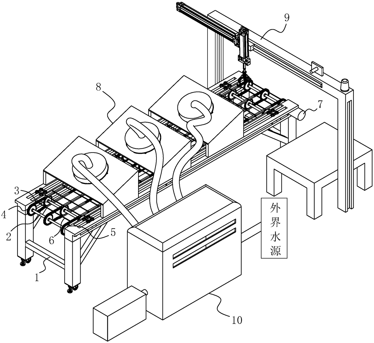
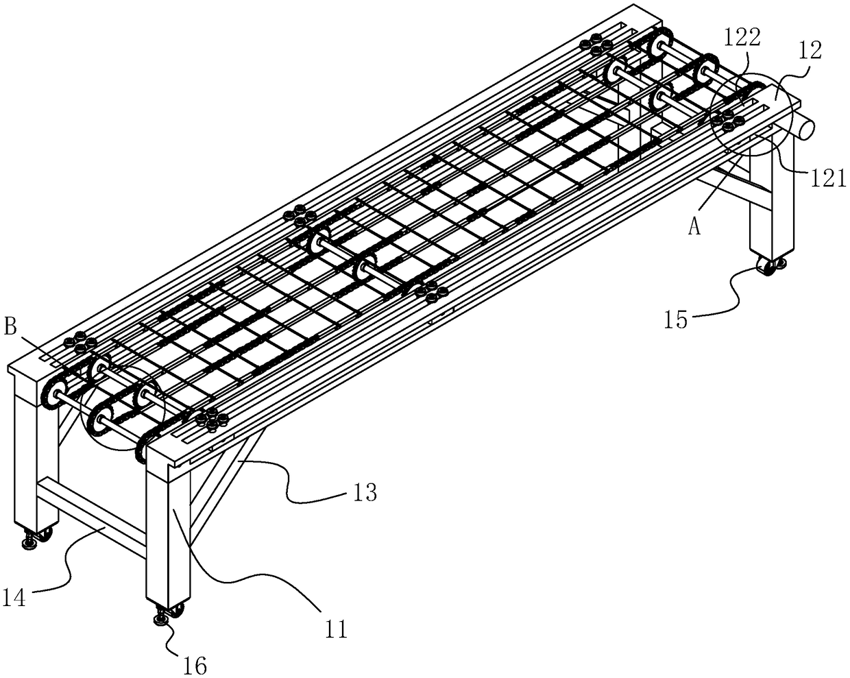
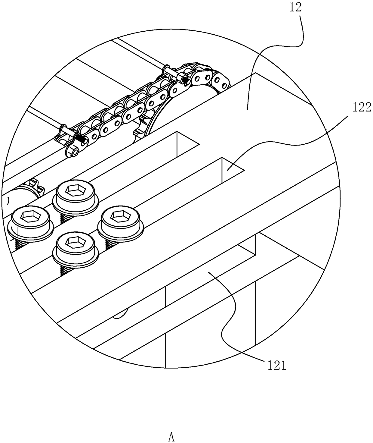
[0049] A die casting conveying device, such as figure 1 As shown, it includes a frame 1 arranged on the ground to play a main supporting role, two first rotating shafts 2 that are respectively arranged at both ends of the frame 1 and are connected to both sides of the frame 1 in rotation, and a plurality of shafts are arranged on the two sides of the frame 1. Between the two first rotating shafts 2 and parallel to the first rotating shafts 2, a plurality of second rotating shafts 3 are evenly distributed on the first rotating shafts 2 and the second rotating shafts 3 and arranged on each of the first rotating shafts 2 and the second rotating shafts. The positions on the two rotating shafts 3 and the sprockets 5 corresponding to the number, a plurality of chains 4 arranged along the length direction of the frame 1 and respectively meshed with the sprockets 5 o...


PUM


Abstract

The invention discloses a die casting conveying device, and relates to a conveying device. The die casting conveying device comprises a frame mounted on the ground, two first rotating shafts rotationally connected to the two ends of the frame, multiple second rotating shafts slidingly connected between the two sides of the frame, multiple chain wheels uniformly distributed on the first rotating shafts and the second rotating shafts, multiple chains engaged with the chain wheels positioned on the same vertical surface, multiple metal strips arranged on all the chains at equal intervals, a motorarranged on one side of the frame and connected with one first rotating shaft through a motor shaft, an air cooling mechanism arranged rightly above the frame and used for accelerating the flowing speed of air on the surfaces of die castings, and a stacking mechanism arranged at the tail end of the frame and used for taking down the die castings from the frame to stack. The die casting conveyingdevice achieves the effect of preventing damage of the conveying device by the die castings with higher temperature.

Description

technical field [0001] The present invention relates to a conveying device, more particularly it relates to a die casting conveying device. Background technique [0002] Die casting is a method of casting liquid die forging, which is a process completed on a special die casting machine. Its basic technological process is: the metal liquid is firstly cast and filled into the cavity of the mold at low or high speed. Loose defects also make the internal structure of the blank reach the broken grains of the forged state. The comprehensive mechanical properties of the blank have been significantly improved. However, after the workpiece is processed, it is necessary to manually remove the workpiece, and there will still be some residual heat after the workpiece has just been processed. It is easy to be scalded if the workpiece is directly picked up manually. Die-casting machine manufacturers are required to develop some reclaiming devices that are used in conjunction with die-ca...

Claims


Application Information

Patent Timeline
Patent Type & Authority Applications(China)
IPC IPC(8): B22D17/20
CPCB22D17/2084
Inventor 孙巧盈
Owner 厦门浙辉工贸有限公司
Why Eureka
Try Eureka