
High-performance electric injection molding device

An injection molding system and injection molding machine technology, applied in the field of plastics, can solve the problems of reduced injection response speed, fast contact surface wear, and great influence of working conditions, so as to reduce the total mass, improve the effect speed and injection precision, and improve The effect of injection acceleration

Pending Publication Date: 2018-12-07
GIENKEE PLAS SCI & TECH SUZHOU
View PDF0 Cites 4 Cited by
  • Summary
  • Abstract
  • Description
  • Claims
  • Application Information

AI Technical Summary

Problems solved by technology

In the current traditional injection molding device, there are many and complicated parts that need to move during the injection process (for example, including screws, servo motors, pre-molded transmission systems, bearing sets, injection nuts, and injection skateboard seats, etc.)
According to Newton's second law, when the injection pressure is constant, if the total mass of the injection motion system is large, the acceleration obtained by the screw will decrease accordingly, that is, the injection response speed will be greatly reduced, and the required injection speed cannot be achieved in a very short time. Injection speed has a great influence on the working conditions required by high-speed injection
In addition, the linear guidance of the moving parts in the traditional injection system is realized by sliding friction. The contact surface wears quickly, generates more heat, requires high lubrication, and crawling occurs when the lubrication is insufficient. At the same time, it also increases the additional power consumed by the drive motor.

Method used


Image

  • High-performance electric injection molding device
  • High-performance electric injection molding device
  • High-performance electric injection molding device

Examples


Embodiment 1

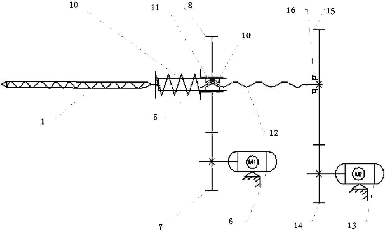
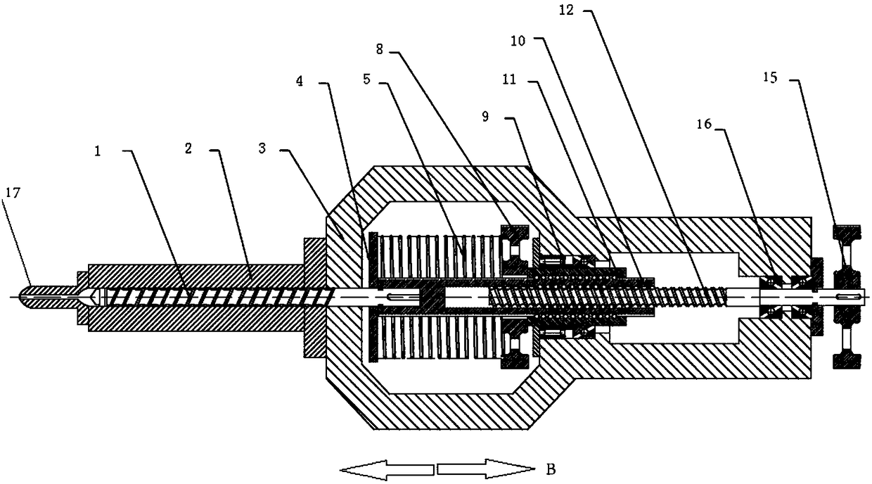
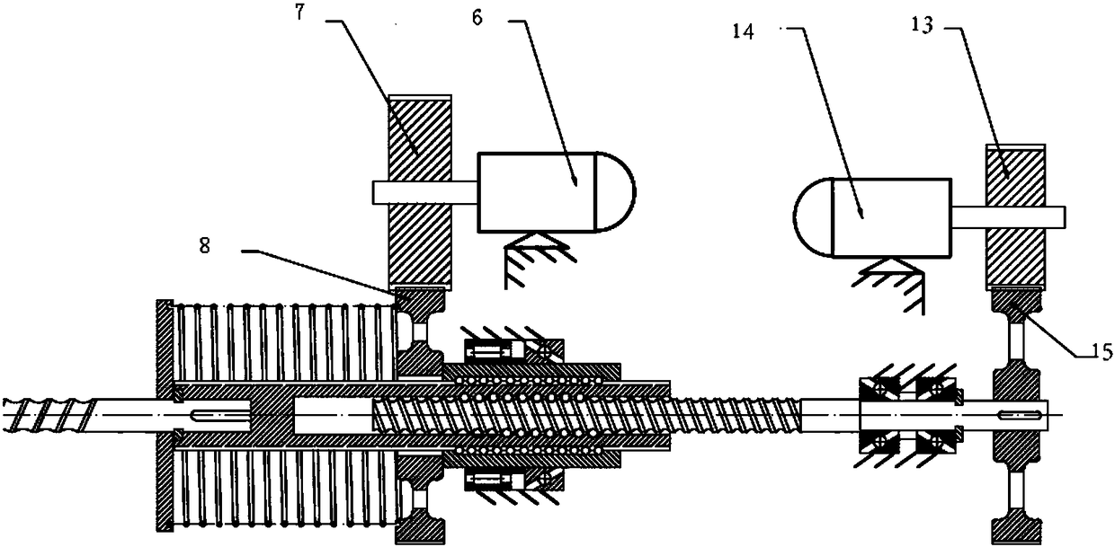
[0044] Below, refer to Figure 1-3 The structure of the injection molding system according to the first embodiment of the present invention will be described.

[0045] figure 1 A schematic diagram of the principle of the injection molding system according to the first embodiment of the present invention is shown.

[0046] figure 2 It is a plan view showing the injection molding system of the first embodiment in section.

[0047] The barrel is 2, the fixed frame is 3, and the fixed frame 3 is used to support the injection molding system. The barrel 2 is fixedly connected to the front end of the fixed frame 3 by bolts, the front end of the barrel 2 is provided with a nozzle 17, and a mold clamping system (not shown in the figure) can be configured in front of the nozzle 17.

[0048] The screw rod 1 that plays the role of pushing out the member, the main body of the screw rod 1 is installed in cooperation with the inner chamber of the barrel 2, and the screw rod 1 can move bac...


PUM


Abstract

The invention provides a high-performance electric injection molding mechanism and an injection molding machine. The injection molding mechanism comprises a screw, a screw driving shaft, a ball screwand an axial guiding mechanism, wherein the screw driving shaft comprises a ball spline and a ball nut. When the injection molding mechanism and the injection molding machine provided by the inventionperform injection action, only a small number of parts, including the screw, the screw driving shaft and the like, need to move, and the other driving and transmission parts do not move axially withthe injection action; and the mechanism has light weight during injection movement, so movement inertia is greatly reduced, and thus, the response speed and accuracy of the injection action are greatly improved, and driving power is also greatly reduced.

Description

technical field [0001] The invention belongs to the field of plastics, and relates to an electric injection molding mechanism used in injection molding machines and the like. Background technique [0002] The consumption rate of the plastics industry has been increasing, therefore, the improvement of the overall technical level of injection molding machines is very important to enhance the competitiveness of the plastics industry. [0003] At present, the injection molding machine mainly includes motors, reduction transmission systems, screws, screw nuts and other components. Among them, the screw is an important part of the injection molding machine, which is used to transport, compact, melt, stir and apply pressure to plastics. All of the above The action is accomplished by the rotation of the screw in the barrel and the movement along the axial direction. When the screw rotates, the plastic will generate friction and mutual motion against the inner wall of the barrel, th...

Claims


Application Information

Patent Timeline
IPC IPC(8): B29C45/50B29C45/58
CPCB29C45/5008B29C45/58
Inventor 陈明华
Owner GIENKEE PLAS SCI & TECH SUZHOU
Learn More