
Movable 3D printing device

A 3D printing and mobile technology, applied to 3D object support structures, metal processing equipment, manufacturing tools, etc., can solve the problems of high cost of 3D printing devices, low exposure resolution of projectors, poor light transmission of liquid crystal panels, etc., to achieve Good light transmittance, high resolution, less quantity effect

Inactive Publication Date: 2018-12-07
SHAOXING FAST REAL ELECTRONICS TECH CO LTD
View PDF0 Cites 3 Cited by
  • Summary
  • Abstract
  • Description
  • Claims
  • Application Information

AI Technical Summary

Problems solved by technology

[0003] 1) The exposure resolution of the projector is low, prone to pattern distortion, and the price of the projector is high, resulting in high cost of the 3D printing device;
[0004] 2) Ordinary array light panels can overcome the problems of distortion and high cost, but there are problems such as poor light transmission of the liquid crystal panel, complex heat dissipation system, poor verticality and poor consistency of projected light

Method used

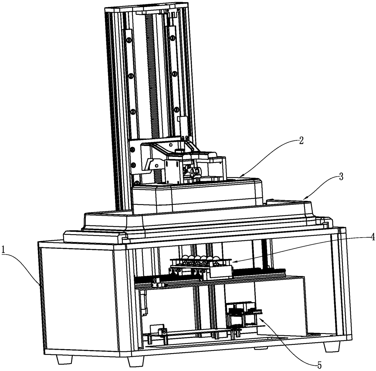

Image

  • Movable 3D printing device
  • Movable 3D printing device
  • Movable 3D printing device

Examples


Embodiment Construction

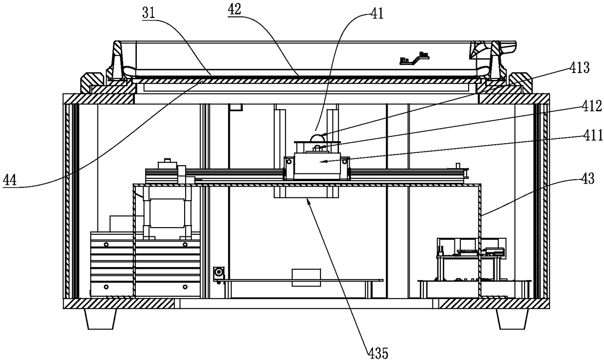
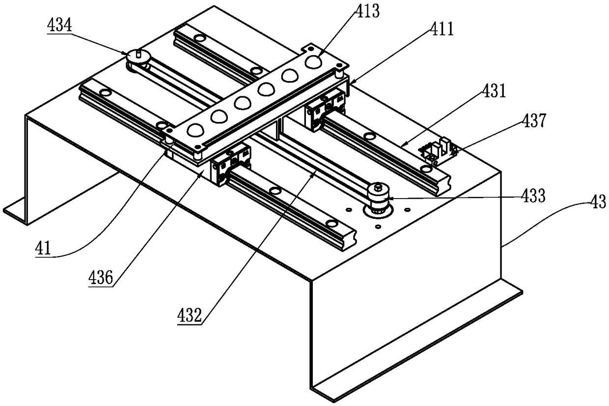
[0025] like Figure 1-3 As shown, a mobile 3D printing device includes a printing mechanism 2 installed on a base 1 , a liquid holding mechanism 3 , an exposure mechanism 4 and a control mechanism 5 . The exposure mechanism 4 includes a bracket 43, a light source assembly 41 slidably arranged on the bracket 43, and a liquid crystal panel 42 arranged in the light source emission direction of the light source assembly 41. The light emitted by the light source assembly is projected to the 3D printing mechanism through the liquid crystal panel 42. At the bottom of the material tank 31 , the control mechanism 5 controls various actions of the exposure mechanism 4 .

[0026] In this embodiment, the light source assembly 41 is strip-shaped, and includes a heat dissipation base 411 for heat dissipation of the light source, a light source 412 mounted on the heat dissipation base 411 , and an optical lens 413 located above the light source 412 . The light source 412 is composed of a pl...


PUM


Abstract

The invention discloses a movable 3D printing device. The movable 3D printing device comprises a printing mechanism, a liquid storage mechanism, an exposure mechanism and a control mechanism, whereinthe printing mechanism, the liquid storage mechanism, the exposure mechanism and the control mechanism are mounted on a base, the exposure mechanism comprises a support, a light source assembly arranged on the support in a sliding mode and a LCD panel arranged in the direction of the light source emitting of the light source assembly, and light rays emitted by the light source assembly is projected onto the bottom of a material groove of a 3D printing mechanism through the LCD panel. The movable 3D printing device has the advantages of being high in printing precision, and good in heat dissipation.

Description

technical field [0001] The invention relates to a mobile 3D printing device, which belongs to the field of printers. Background technique [0002] A 3D printing device generally includes a printing mechanism, a liquid holding mechanism, an exposure mechanism and a control mechanism, and is used to realize three-dimensional printing of 3D objects. At present, the exposure mechanism of conventional 3D printing devices generally uses projectors or ordinary array light panels for exposure, and there are mainly the following problems: [0003] 1) The exposure resolution of the projector is low, prone to pattern distortion, and the price of the projector is high, resulting in high cost of the 3D printing device; [0004] 2) Ordinary array light panels can overcome the problems of distortion and high cost, but there are problems such as poor light transmission of the liquid crystal panel, complex heat dissipation system, poor verticality and poor consistency of projected light. ...

Claims


Application Information

Patent Timeline
Patent Type & Authority Applications(China)
IPC IPC(8): B29C64/124B29C64/264B33Y30/00
CPCB29C64/124B29C64/264B33Y30/00
Inventor 张靖金良陈明金伟刚高中宇
Owner SHAOXING FAST REAL ELECTRONICS TECH CO LTD
Learn More