
A closed isobaric compressed air energy storage system and method

A compressed air energy storage and equal pressure technology, which is applied in the pipeline system, gas/liquid distribution and storage, liquid variable capacity machinery, etc., can solve the problems of reducing system economy, low economy, system complexity, etc., and achieve improvement Efficiency and economy, improvement of system economy, effect of system efficiency improvement

Active Publication Date: 2020-03-17
XI AN JIAOTONG UNIV
View PDF9 Cites 1 Cited by
  • Summary
  • Abstract
  • Description
  • Claims
  • Application Information

AI Technical Summary

Problems solved by technology

Under the same gas storage pressure, the open cycle leads to problems such as high pressure ratio of the compressor unit, long compression process, serious heat generation, etc., so it is necessary to design a complex cooling system and use multi-stage compression to reduce the compressor capacity of each stage. In addition, the existing compressed air energy storage systems often use throttle valves to stabilize the air pressure at the outlet of the high-pressure gas storage tank, which will cause great Throttling loss, reducing system economy

Method used


Image

  • A closed isobaric compressed air energy storage system and method

Examples


Embodiment 1

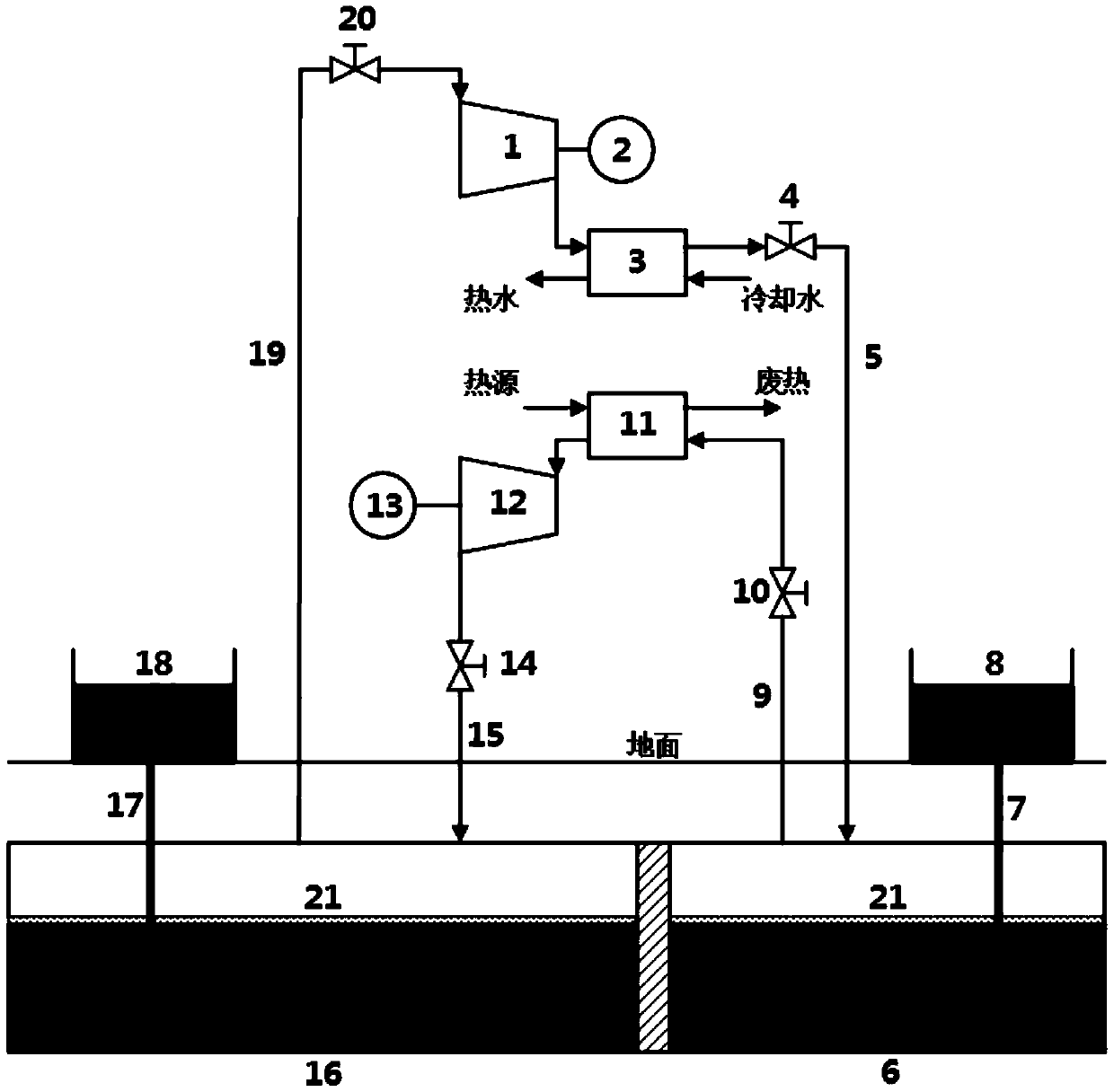
[0033] The present invention is a closed isobaric compressed air energy storage system, such as figure 1 As shown, it includes a compressor unit 1 driven by a motor 2, a generator 13 driven by an expansion unit 12, a high-pressure gas storage chamber 6, a high-pressure liquid storage tank 8, and a high-pressure infusion fluid connected to the high-pressure gas storage chamber 6 and the high-pressure liquid storage tank 8 The pipeline 7, the low-pressure gas storage chamber 16, the low-pressure liquid storage tank 18 and the low-pressure infusion pipeline 17 connecting the low-pressure gas storage chamber 16 and the low-pressure liquid storage tank 18;

[0034] The inlet of the low-pressure gas storage chamber 16 is connected to the outlet of the expansion unit 12 through the exhaust pipe 15 , and the outlet of the low-pressure gas storage chamber 16 is connected to the inlet of the compressor unit 1 through the intake pipe 19 . The inlet of the high-pressure gas storage chambe...

Embodiment 2

[0041] A closed isobaric compressed air energy storage method of the present invention comprises the following steps:

[0042] Step 1, before energy storage:

[0043] Since the high-pressure gas storage chamber 6 communicates with the high-pressure liquid storage pool through the high-pressure infusion pipeline 7, and there is no air stored in the high-pressure gas storage chamber 6 before the energy storage begins, so the high-pressure gas storage chamber 6 is filled with liquid at this time.

[0044] Step 2, energy storage stage:

[0045] Open the intake valve 20 and the gas storage valve 4. The air in the low-pressure gas storage chamber 16 is sent into the compressor unit 1, and the motor 2 drives the compressor unit 1 to compress the air. The air at the outlet of the compressor unit 1 is sent into the high-pressure gas storage chamber 6 through the gas storage pipeline 5, and the high-pressure gas is discharged into the high-pressure gas storage chamber 6. The liquid in...


PUM


Abstract

The invention provides a closed type isobaric compressed air energy storage system and method. The system comprises a compressor set, a motor, a high-pressure gas storage chamber, a high-pressure liquid storage tank and an expansion set, a generator, a low-pressure gas storage chamber and a low-pressure liquid storage tank; an outlet of the low-pressure gas storage chamber communicates with an inlet of the high-pressure gas storage chamber through the compressor set, an outlet of the high-pressure gas storage chamber communicates with an inlet of the low-pressure gas storage chamber through the expansion set, so that a closed loop is formed; the low-pressure gas storage chamber is connected with the low-pressure liquid storage tank through a low-pressure liquid conveying pipeline, and thehigh-pressure gas storage chamber is connected with the high-pressure liquid storage tank through a high-pressure liquid conveying pipeline; and the compression net is provided with the motor; and theexpansion set is provided with the generator. According to the system and the method, the expansion ratio of the expansion set of the system is reduced, and air is fully expanded in each stage of expansion machines; and the complexity of the system is reduced, the pressure loss caused by a throttling pressure-stabilizing valve of a traditional compressed air energy storage system is eliminated, the compressor set and the expansion set of the system can be operated under a stable working condition, and the efficiency and economical efficiency of the system are improved.

Description

technical field [0001] The invention relates to the field of electric energy storage utilization, in particular to a closed isobaric compressed air energy storage system and method. Background technique [0002] China's fast-growing economy cannot do without the support of energy. As the world's largest energy consumer, China needs to increase energy conservation and emission reduction efforts to alleviate environmental pollution caused by the extensive use of fossil fuels. [0003] The development of new energy brings hope for the clean utilization of energy. However, the existing clean energy such as wind energy and solar energy has a certain degree of volatility. It is difficult for wind farms to ensure sufficient air volume 24 hours a day. Solar power plants cannot generate electricity at night, and the volatility of wind power also prevents them from being directly connected to the grid for power generation. [0004] Energy storage technology is regarded as an effecti...

Claims


Application Information

Patent Timeline
Patent Type & Authority Patents(China)
IPC IPC(8): F01K27/00F01K25/08F17D3/01F04B35/04
CPCF01K25/08F01K27/00F04B35/04F17D3/01
Inventor 王焕然刘明明李丞宸严凯张淑宇李瑞雄
Owner XI AN JIAOTONG UNIV
Learn More