Self-locking flow regulating needle valve

A flow adjustment and self-locking technology, which is applied in the direction of valve lift, valve details, valve device, etc., can solve the problems of valve stem not being able to self-lock, valve stem seal is easily damaged, and flow rate changes unexpectedly, so as to achieve good self-locking ability , Eliminate pressure fluctuations, the effect of small torque

Active Publication Date: 2018-12-07
安庆泰邦船舶科技有限公司
View PDF6 Cites 3 Cited by
  • Summary
  • Abstract
  • Description
  • Claims
  • Application Information

AI Technical Summary

Problems solved by technology

[0003] The technical problem to be solved by the present invention is that the flow regulating needle valve in the prior art uses a rotating handwheel, which is likely to cause misoperation and cause unexpected flow adjustment Changes, the valve core and the valve stem rotate together, it is impossible to achieve micro-adjustment, the seal of the valve stem is easily damaged, and the valve stem cannot be self-locked, etc.

Method used


Image

  • Self-locking flow regulating needle valve
  • Self-locking flow regulating needle valve
  • Self-locking flow regulating needle valve

Examples


Embodiment Construction

[0032] The embodiments of the present invention are described in detail below. This embodiment is implemented on the premise of the technical solution of the present invention, and detailed implementation methods and specific operating procedures are provided, but the protection scope of the present invention is not limited to the following implementation example.

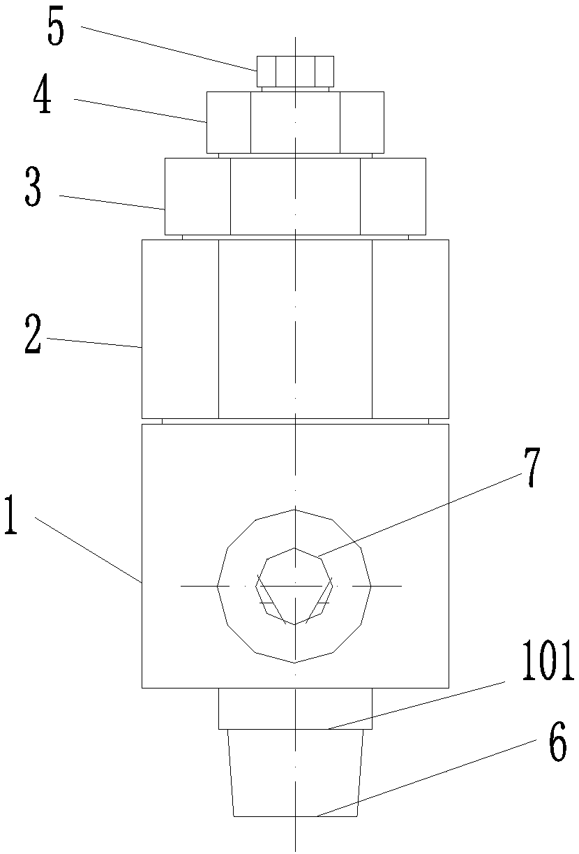
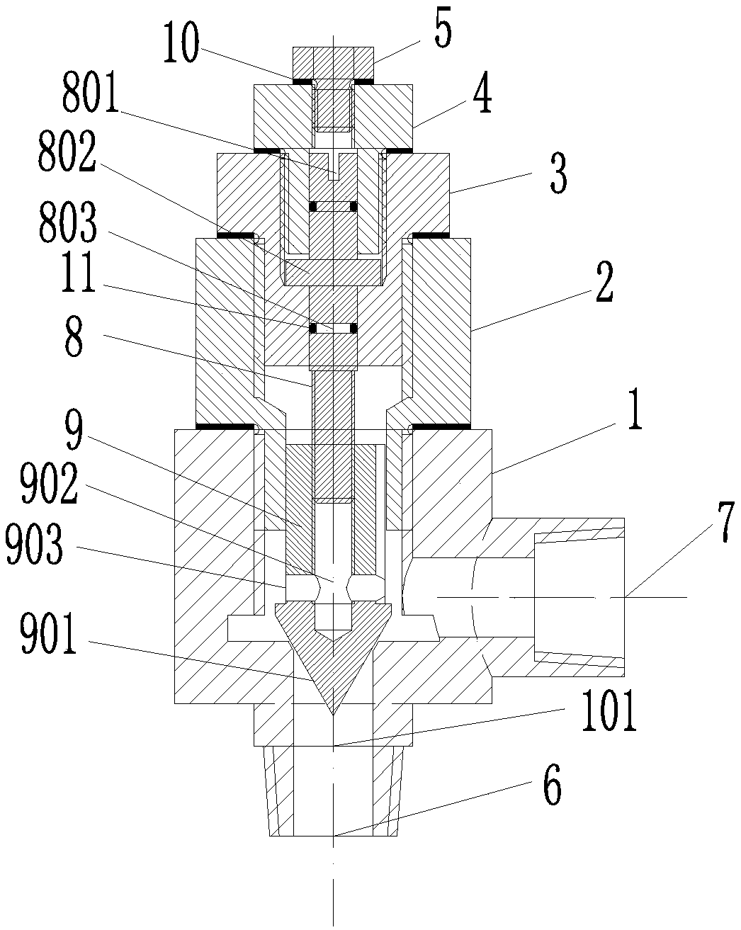
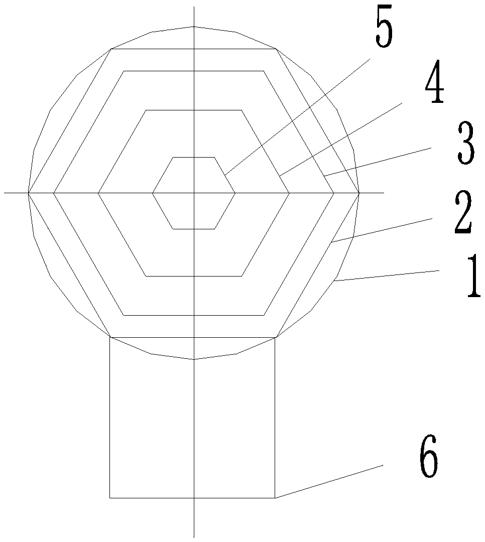
[0033] Such as Figure 1-3 As shown, a self-locking flow regulating needle valve includes a valve seat 1, a guide seat 2, a valve stem seat 3, an upper cover 4, a plug 5, a fluid inlet 6, a fluid outlet 7, a valve stem 8, and a valve core 9 , Gasket 10 and O-ring 11.

[0034] The valve seat 1, the guide seat 2, the valve stem seat 3 and the upper cover 4 are all of an inverted convex structure with a coaxial hollow cylinder inside and with an upper concave surface and a lower convex surface. The plug 5 is a convex structure with a lower convex surface, the lower convex surface of the plug 5 is fixedly connected i...


PUM


Abstract

The invention discloses a self-locking flow regulating needle valve. The self-locking flow regulating needle valve comprises a valve seat, a guide base, a valve rod base and an upper cover, wherein achoke plug is fixedly connected in the upper cover; the upper cover is fixedly connected in the valve rod base; the valve rod base is fixedly connected in the guide base; the guide base is fixedly connected in the valve seat; the lower end of the valve seat is provided with an inlet; the inlet communicates with a fluid inlet; a fluid outlet is transversely formed in the side surface of the valve seat; the upper end of the valve rod is movably blocked in the upper cover and the valve rod base; the valve element is in threaded connection to the lower end of the valve rod; the outer edge of the valve element is blocked to the lower end of the guide base; the lower end of the valve element is equipped with the needle valve; and the needle valve is movably blocked to the lower-end inlet of thevalve seat. The self-locking flow regulating needle valve has the advantages of being micro in regulation, good in sealing effect, capable of being self-locked and the like.

Description

technical field [0001] The invention relates to a flow regulating needle valve, more specifically to a self-locking flow regulating needle valve. Background technique [0002] Flow adjustment is required in industrial pipelines. The manual flow control valve currently used basically uses the rotating handwheel to make the valve stem and valve core rotate together, and adjust the gap between the valve core and valve seat to achieve the purpose of flow adjustment. . Such a structure will cause many problems in actual use, such as rotating the handwheel, which is more convenient for adjustment, but in actual use, human misoperation often occurs, or the on-site personnel accidentally touch the handwheel, which will cause poor adjustment. Unexpected changes in the flow rate will affect the stable operation of the pipeline system; secondly, the valve stem and the valve core rotate together, the accuracy of the thread is affected by the structure, the positioning stability is not ...

Claims


Application Information

Patent Timeline
Patent Type & Authority Applications(China)
IPC IPC(8): F16K27/08F16K1/42F16K1/38F16K1/32F16K1/46
CPCF16K1/32F16K1/38F16K1/42F16K1/46F16K27/08
Inventor 张志华
Owner 安庆泰邦船舶科技有限公司
Why Eureka
Try Eureka