Portable CO2 monitoring device and method for seismic precursor flow observation

A monitoring device and portable technology, which is applied in the field of portable CO2 monitoring devices for earthquake precursor flow observation, can solve the problems of poor environment for earthquake precursor flow observation, inability to obtain concentration, timeliness, and poor accuracy on site, and achieve multiple Parameter measurement, improvement of environmental adaptability and environmental anti-interference performance, and high accuracy

Pending Publication Date: 2018-12-07
杭州超钜科技有限公司
View PDF6 Cites 1 Cited by
  • Summary
  • Abstract
  • Description
  • Claims
  • Application Information

AI Technical Summary

Problems solved by technology

Gas chromatography is to obtain CO through on-site sampling and laboratory testing. 2 Concentration, this method cannot obtain the concentration on site, the timeliness is poor and the error of manual sampling is large
The chemical method is to obtain CO by measuring the pH value through a measuring tube containing thymolphthalein. 2 Concentration, this method detects the accumulated amount over a period of time, and artificial estimation leads to large errors in the detection results, so the timeliness and accuracy are poor
CO measurement with infrared sensor 2 Concentration has been widely used in environmental protection, safety, medical and other industries. This method has fast response, continuous observation and wide measurement range, but it cannot meet the harsh environment, low background concentration, wide measurement range, low power consumption, and small size needs

Method used


Image

  • Portable CO2 monitoring device and method for seismic precursor flow observation
  • Portable CO2 monitoring device and method for seismic precursor flow observation
  • Portable CO2 monitoring device and method for seismic precursor flow observation

Examples


Embodiment

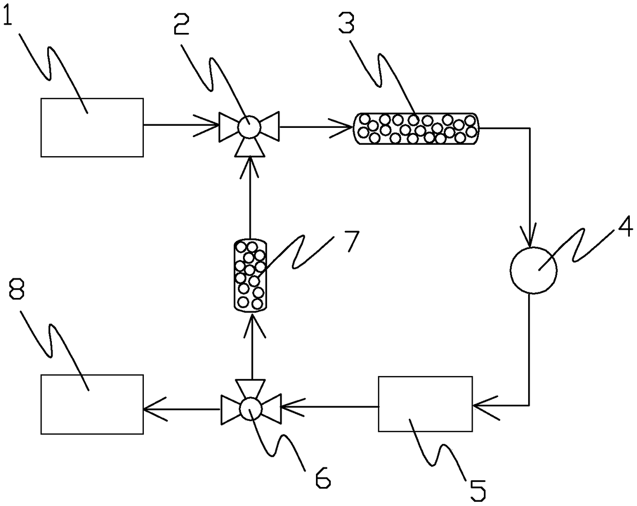
[0022] Embodiment: Portable CO for earthquake precursor flow observation in this embodiment 2 monitoring devices such as figure 1 As shown, it includes air inlet 1, first solenoid valve 2, dehumidification device 3, flow controller 4, CO 2 Sensing detection unit 5, second solenoid valve 6, purification device 7, air outlet 8 and main control circuit, air inlet, first solenoid valve, dehumidification device, flow controller, CO 2 The sensing unit, the second solenoid valve and the gas outlet are connected in sequence, one end of the purification device is connected with the first solenoid valve, and the other end of the purification device is connected with the second solenoid valve. Air inlet, first solenoid valve, dehumidification device, flow controller, CO 2 The sensing detection unit, the second solenoid valve and the gas outlet constitute the measuring gas path; the first solenoid valve, dehumidification device, flow controller, CO 2 The sensing detection unit, the sec...


PUM

PropertyMeasurementUnit
diameteraaaaaaaaaa
lengthaaaaaaaaaa
pore sizeaaaaaaaaaa

Abstract

The invention relates to a portable CO2 monitoring device and method for seismic precursor flow observation. The monitoring device comprises an air inlet, a first electromagnetic valve, a dehumidifying device, a flow controller, a CO2 sensing detecting unit, a second electromagnetic valve, a purifying device, an air outlet and a main control circuit. The air inlet, the first electromagnetic valve,the dehumidifying device, the flow controller, the CO2 sensing detecting unit, the second electromagnetic valve and the air outlet are orderly connected. The purifying device is connected between thefirst electromagnetic valve and the second electromagnetic valve. The first and second electromagnetic valves and the CO2 sensing detecting unit are respectively connected to the main control circuit. The device comprises a measuring gas path and a self-calibrating circulating gas path. The CO2 sensing detecting unit has an integrated design based on an infrared absorption principle, has a high detection limit and a fast response speed, can correct the CO2 concentration based on an environmental factor through multi-parameter measurement and can improve the accuracy of CO2 concentration detection. The device is small in size, is easy to carry and can be used in the harsh environment at the earthquake precursor observation point.

Description

technical field [0001] The present invention relates to a CO 2 Monitoring equipment, especially a portable CO 2 Monitoring device and monitoring method. Background technique [0002] The process of earthquake breeding and occurrence will affect the CO 2 Distribution and migration on the surface, changing CO in crustal outgassing 2 Release dynamics, so monitoring of CO release from fault zones, thermal springs or thermal wells 2 Dynamics is a new way to explore earthquake prediction. my country's limited CO 2 Dynamic monitoring data show that CO 2 in some M s ≥4.0 There are obvious abnormal reflections before the earthquake. Therefore, it is widely established that subsurface fluid CO 2 Observation points are conducive to the development of earthquake precursor observation technology. [0003] Traditional seismic precursor flow CO 2 Observation mainly adopts gas chromatography or chemical method. Gas chromatography is to obtain CO through on-site sampling and labo...

Claims


Application Information

Patent Timeline
Patent Type & Authority Applications(China)
IPC IPC(8): G01N21/3504
CPCG01N21/3504
Inventor 何镧刘佳琪
Owner 杭州超钜科技有限公司
Why Eureka
Try Eureka