
Data point merging based frequency modulated continuous wave radar target parameter estimation method

A frequency-modulated continuous wave and parameter estimation technology, which is applied to radio wave measurement systems and instruments, can solve problems such as large parameter estimation errors and inaccurate determination of the number of targets, and achieve the effect of improving the distance

Active Publication Date: 2018-12-07
杭州岸达科技有限公司
View PDF4 Cites 2 Cited by
  • Summary
  • Abstract
  • Description
  • Claims
  • Application Information

AI Technical Summary

Problems solved by technology

[0004] The purpose of the present invention is to overcome the deficiencies of the above-mentioned prior art, and provide a method for estimating target parameters of frequency modulation continuous wave radar based on data point merging, which aims to solve the problem of inaccurate determination of the number of targets and large parameter estimation errors in the prior art. technical problem

Method used


Image

  • Data point merging based frequency modulated continuous wave radar target parameter estimation method
  • Data point merging based frequency modulated continuous wave radar target parameter estimation method
  • Data point merging based frequency modulated continuous wave radar target parameter estimation method

Examples


Embodiment 1

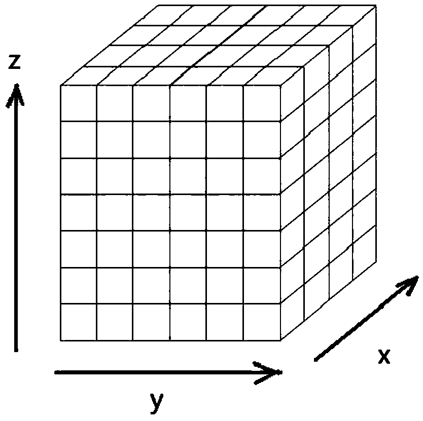
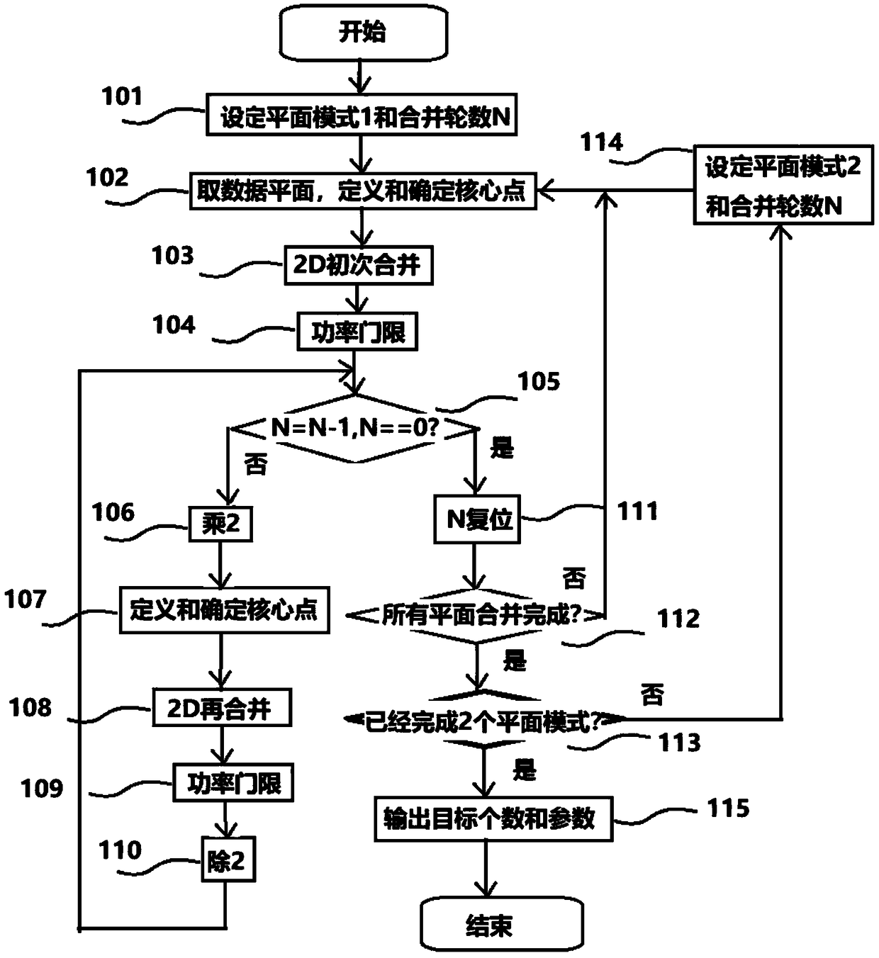
[0067] see Figure 1-7 , an embodiment of the present invention provides a target parameter estimation method based on data point merging provided by the present invention. like image 3 As shown, the method consists of the merging of two planar modes.

[0068] Step 101: Determine the plane mode 1, and the merging will be performed on all the planes thus divided. In the following description of the merging method, only the x-y plane mode is used as an example. Set the number of merge rounds N.

[0069] Step 102 , take a two-dimensional data plane in the determined plane mode, define the requirements of core points, and determine which data points are core points.

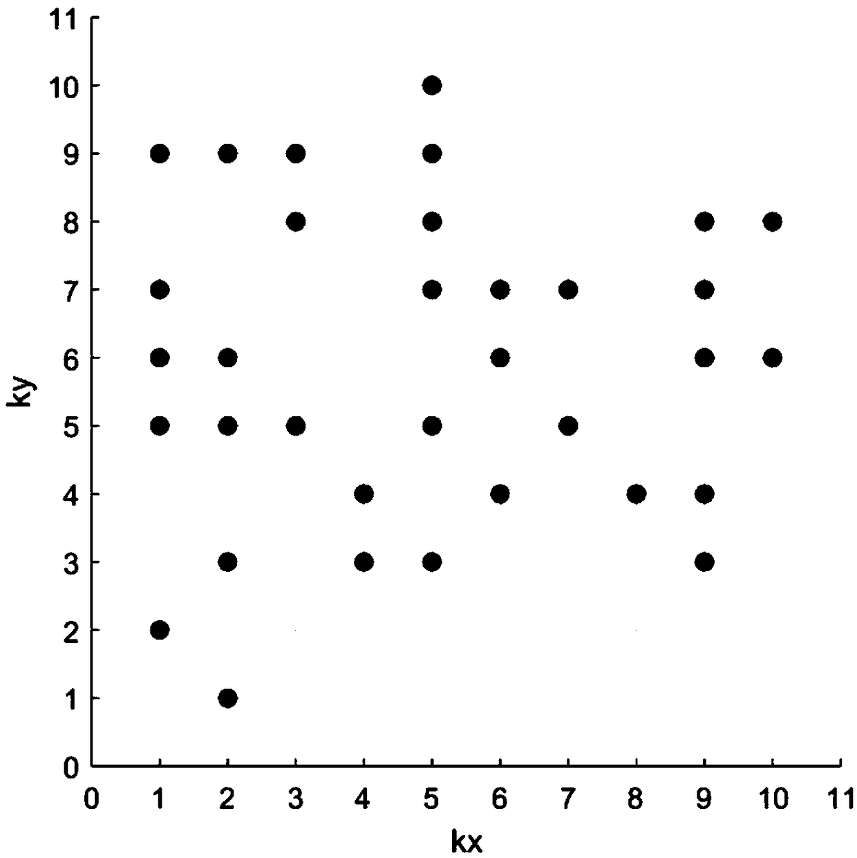
[0070] Step 103, the two-dimensional data is merged for the first time. Merge adjacent core points to get the target point. Definition: If the core point P1 with the value (kx1,ky1) and the core point P2 with the value (kx2,ky2) satisfy:

[0071] |kx1–kx2|<=1 and |ky1–ky2|<=1

[0072] Then P1 and P2 merge ad...

Embodiment 2

[0106] The second implementation method provided by the present invention is to directly perform three-dimensional merge processing on the data cube grid data. Figure 8 A schematic diagram of the method flow. The processing method including the merging criterion is directly generalized from the aforementioned two-dimensional merging method. At this time, the data points and the core points participating in the merge are three-dimensional (kx, ky, kz) data. Therefore, the expansion / compression process of step 206 / step 210 is for kx, ky and kz.

[0107] Step 203, the first three-dimensional merge. Merge adjacent core points to get the target point. Definition: If the core point P1 with the value (kx1,ky1,kz1) and the core point P2 with the value (kx2,ky2,kz2) satisfy:

[0108] |kx1–kx2|<=1 and |ky1–ky2|<=1 and |kz1–kz2|<=1

[0109] Then P1 and P2 merge adjacent core points for the first time. The three-dimensional initial merger criteria are as follows:

[0110] 1) Merge...


PUM


Abstract

The invention provides a data point merging based frequency modulated continuous wave radar target parameter estimation method. An input is a grid coordinate value of a three-dimensional feature datapoint of an echo signal, and an output is an estimated grid coordinate value of each target. The distance, velocity and orientation corresponding to the output grid coordinate values are the estimatedvalues of the target parameters. According to the data point generation mechanism, adjacent data points are merged into one target point, and the merged result can be merged again as input data of the next round of merge processing. The method can distinguish a target with very small parameter spacing, thereby correctly determining the target number and improving the estimation accuracy of the distance, the velocity and the orientation.

Description

technical field [0001] The invention relates to the technical field of estimating target parameters of a frequency modulated continuous wave (FMCW) radar, in particular to judging the number of targets and estimating the target distance, speed and azimuth parameters by merging the data points of the three-dimensional characteristics of the FMCW radar echo signal Methods. Background technique [0002] The three-dimensional features of the echo signals are the basis for the estimation of the target parameters of the FM continuous wave radar. Specifically, two-dimensional fast Fourier spectrum analysis (ie, range FFT and Doppler FFT) is performed on the echo difference frequency signals of multiple frequency sweep cycles at a certain azimuth angle, and the grid coordinates corresponding to each power peak value A point, that is, the distance and Doppler sampling points, expressed in grid coordinates and power values, is a data point. All data points form a raster data plane. ...

Claims


Application Information

Patent Timeline
Patent Type & Authority Applications(China)
IPC IPC(8): G01S7/41
CPCG01S7/41
Inventor 邱万智张远辉郑海树张凡
Owner 杭州岸达科技有限公司
Learn More